Sounds like nozzle design theory where the horn throat is tapered, then basically flips out to 'x' degrees such as this BLH variant.
No, AFAIK it would start at (I assume) a parabolic flare at 'X' degrees per nozzle design theory, but have only done traditional nozzles, so just trying to visualize what your variant might be 'close enough'.
I definitely got lost in the details somewhere back at the beginning of this thread. This is what I get with a centered 1" source in Vituixcad. So vertical baffle height does effect the horizontal off axis!?
32w x 26h

32w x 4h

32w x 26h
32w x 4h
Seems to same as in this app: https://www.diyaudio.com/community/threads/ikea-unity-horn.409719/post-7821942

Didn't intend to veer off topic, especially since I've yet to settle on a horn for the main system, but I bumped into this big thread; clearly one of yours and Weltsys's favorites. https://www.diyaudio.com/community/...l-low-distortion-with-a-2-way.334757/page-676Last I checked I was and inch ore 2 away from 1/4wl coupling between my tweeter and woofers, and it is a benefit. I could only sense the vocals wandering to the lower axis with Barry White.
Your HT system? If yes, about the design of what looks like a center channel speaker under the TV movie dialogue/effects: From what I've read the drivers in a center speaker should be close to the same as those in the main (MTM?) speakers. As they are obviously not the same how does this impact what you hear from the center vs. the main speakers?
In any case, unlike most here, I would have buy a commercial center channel speaker, however well they would work with the mains to build a 3,1 system. https://www.crutchfield.com/g_12100/Center-Channel-Speakers.html?tp=189&pg=2&fa=1#&price=1910-4010
Not that I'm at all prioritizing movie sound over music listening quality, but with the speakers ~ 8 ft apart, the 65" (57" wide) TV in between, but 10" behind the ~ 2 ft deep speakers which are 2ft from front wall and with me sitting ~ 10 ft from TV screen, might you have any recommendations for a center speaker placed below the TV? And would one or more horn type for the mains work better with it?
Put another way, which mains horn might work (almost) equally well for critical stereo/mono music listening and for 3.1 home theater?
https://www.audioheritage.org/vbulletin/showthread.php?31481-Are-Iwata-horns-that-good
https://exclusive-audio.jp/en/produ...UlrNo9mZj1W2blrSpPdTxbT7vU3bt6DRwHuTxFXMQnQ27
https://exclusive-audio.jp/en/produ...kO2Qsk_XOsTAMx0VyaaNGPc79bGp20OSJEoFIf4egjr3A
https://josephcrowe.com/products/3d-cad-plans-for-es-290-biradial-horn-horn-no-1670
https://cdn.shopify.com/s/files/1/0...BMS_4591-8_off-axis3_480x480.png?v=1649504045
https://josephcrowe.com/products/3d-cad-files-horn-no-1994-es450-biradial-for-jbl-2446-2-throat
https://cdn.shopify.com/s/files/1/0...ot_2023-10-14_170306_480x480.png?v=1697317415
AH-425 https://www.diyaudio.com/community/attachments/ah425_field_-gif.128080/
Decided to play with this outdoor measurement. The dip at 210ish should go away with internal damping material. I think this is decent enough for a 200hz xo. The target is a 200hz 24db LR. The measurement is at 3ft ~15inches above the ground. The slot covered on the top/bottom with a baffle.


I keep thinking of possibly changing things, but I cannot see a benefit. MTM is a thing that interest me, but I really like being able to use only 2 amplifier's. The low crossover owns me. Fixing way more issues than it causes. My only motivation to not use the slot being the ability to try higher crossovers. I still have the 15" box. I wonder about a MTW. 200-700hz XO above and 200hz XO below. Sounds pretty practical but then I'd have to use another amplifier. With the 1meter listening distance requirement I've created I have to keep an I on directivity.

I hold my protractor to the front of the baffle I am just within the sweet spot at ~30 degrees. The slot helps to keep things pretty wide, the sweet spot is about 50degrees +/- horizontally around 200hz.

I keep thinking of possibly changing things, but I cannot see a benefit. MTM is a thing that interest me, but I really like being able to use only 2 amplifier's. The low crossover owns me. Fixing way more issues than it causes. My only motivation to not use the slot being the ability to try higher crossovers. I still have the 15" box. I wonder about a MTW. 200-700hz XO above and 200hz XO below. Sounds pretty practical but then I'd have to use another amplifier. With the 1meter listening distance requirement I've created I have to keep an I on directivity.
I hold my protractor to the front of the baffle I am just within the sweet spot at ~30 degrees. The slot helps to keep things pretty wide, the sweet spot is about 50degrees +/- horizontally around 200hz.
The VOTT still continues to hold interest, this project from a year ago, is pretty neat.

If I want the remove damping material from the slot, this is real and sure fire way to do it. The issue of resonating thread rod is also taken care, as they only need to be long enough to connect the woofers. I need to come up for a bracing solution of wood that allows access to the woofers, from the front panels, but its completely doable.
Particles speed looks well under control.
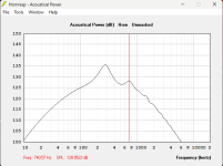
I am worried about is Pascals. I will be basically cutting the exposed area of the woofers in half. So about 600cm2 exposed of the 1200cm2 diaphragm. According to winISD the pascals are as graphed below. I placed 20hz at 115db/1m the place to criticize.
Everything is probably fine, but I would like to understand better how many pascals can a driver typically tolerate? @weltersys @GM @b_force
Last edited:
https://sengpielaudio.com/calculator-soundlevel.htmI am worried about is Pascals.
One atmosphere is ~1 Pascal, the little red dot to the right of the Pascal/dB "thermometer".
No problem.I will be basically cutting the exposed area of the woofers in half. So about 600cm2 exposed of the 1200cm2 diaphragm.
You probably could put the pair of 18" with a plenum exit of 600cm2 without a problem.
Easy to check, just clamp some boards to your cabinet and test it out with the reduced exit and plenum volume.
I converted a single 12" cabinet to a 2x10" with a slot only 3/4" wide, a much tighter restriction than you seem to be thinking about, it worked OK.
That said, eventually found ~450 watts of compressed drum mix per 150watt driver was a bit too much for the 2" voice coils 😳 .
Lots, the SPL inside a compression driver or sealed woofer enclosure can reach over 160dB.Everything is probably fine, but I would like to understand better how many pascals can a driver typically tolerate?
Art
The slot its self doesn't have to change, looking at the terminus CSA. The woofer would be facing a half circle is all, in order to bring forth the rear wall of the slot.You probably could put the pair of 18" with a plenum exit of 600cm2 without a problem.
As you already know my habits, here is the alternative to changing the slot that is stalling me
vs
One thing about resonances issues is that EQ doesn't always fix them. Damping material definitely helps, but with the short slot, damping material is no longer an effective option. Damping material with the current slot looks very smooth in the simulation.
Attachments

Quickly learned quickly forgotten... I had to double check this because I forgot what I'd discovered. I think this is completely useful information as these are the aspects of judging a loudspeakers dynamic performance.What in particular are you looking at? the 116db measurement, would have a true peak of 119db btw. 115db/1m was my goal post and if true peak is 3db over measurement average, in stereo, a measurement at 109db per channel would be the adequate measurement. True peak would be 112db per channel and in stereo it would hit 115db true peak... the data below at 3.53v would slightly more than enough to hit those numbers... with THD this low, transients are still still fine, I would think... and the transient accuracy is really the thing to care about.
View attachment 1282188
First, realize that you cannot fully access the THD performance of a compression driver while its on a horn. Directivity and Horn Resonance get in the way of what's actually happening at the driver when measured at the mouth of the horn. Drastically high spl levels within the horns throat won't allow measurements to be taken at the drivers exit. The only way to view THD performance clearly is to voice the driver while its on the horn, and then remove the horn, and take measurements as close as possible to the exit. An easy way to go about it is to have 2 drivers, one with horn and one with no horn, so you can Experiment with voicing on the Horned driver and test THD on the driver with no horn. This is useful in the cutoff area of a horns performance where there is the issue of the Horn losing resonance which changes the ratio of harmonics vs fundamental as well as bring SPL closer and closer to the noise floor and potentially below as well as potential higher Resonance and Directivity of the higher order harmonics.
"With a pure sine wave, the true peak is precisely 3.0 dB higher than the RMS value. This is a fundamental property of sine waves, where the peak amplitude is the square root of 2 times the RMS amplitude"
Below Shows the RTA of REW displaying a measurement in purple. The Red is the live RTA peak hold after playing around with the Signal generator use my mouse to sweep slowly. The gain stages are set at -20dbfs on measurements and signal generator. Using the REW SPL meter, LZFmax/min track the recorded measurement within 0.1db and the TruePeak shows the typical +3db over RMS. If Looking to criticize the dynamic performance of a system, this is critical information. I have not come to a conclusion how use this information to its fullest extent but this is what we can be certain of. The True Peaks are raising the THD levels of the RMS THD measurement. The RMS THD measurements are not showing the True Peaks of THD. The True Peaks are likely causing the RMS THD levels to be higher but on the same note the True Peak nature of THD is not being shown.
All is not lost. Understanding the data is half the battle. I think that True Peak signal and the THD it causes will be reflected in the RMS of THD signal to an extent, but we have to assume that the True Peaks of the THD itself are not include in the REW THD reading. You can try using the RTA to get a better glimpse. With the FFT size set to 8k, and the "show distortion" turn on, you can capture higher peaks in the THD. For example the real time reading allows me to see 2nd Order THD as high as 0.66% vs the 0.202% in the initial REW measurement. Matter of fact, taking several repeated rew measurements might help you capture higher levels of THD.
Another important aspect is "THD quantifies the level of harmonic distortion present in a signal, but it doesn't directly indicate whether the fundamental itself is distorted. The fundamental can retain its original shape even in the presence of significant harmonic distortion."
vs
So there are other approaches to analysis of dynamic performance. Once again, if choosing to use the Oscilloscope or record the waveform in an audio recording program. I think miking the un-Horned driver would be most accurate.
You can "fully access" performance of a horn/driver, or that of a raw driver.First, realize that you cannot fully access the THD performance of a compression driver while its on a horn.
Obviously, a raw driver will have a different THD, frequency and impulse response profile than when it is attached to a horn.
If you want to measure your compression drivers without horns, go ahead, but it won't give you any useful information that would be applicable to your system.
You mentioned that months ago, appears you still haven't tried it.Damping material with the current slot looks very smooth in the simulation.
Untrue. The horn does not change the excursion of the compression driver. The changes in thd while on the horn reflect that truth. By monitoring thd with the horn removed we can see the true nature of the diaphragms performance. When a driver moves into outer stretches of excursion the thd that is caused as a result, is parasitic to Higher frequencies produced by the driver at the same time. When you see high thd as reported with the horn this relationship isn't always true. The horn creates situations as I explained above, that lead to high thd readings of LF but this thd isn't represented by true non linearity that would pollute the rest of upper spectrum.If you want to measure your compression drivers without horns, go ahead, but it won't give you any useful information that would be applicable to your system.
Which situation would prefer and why?You mentioned that months ago, appears you still haven't tried it.
Correction, Waveguides don't change the excursion of the compression driver, horns don't change excursion, much....
waveguide


Horn


When judging THD with horn off, you can find the limitations of Voltage per Voicing. When you attach the horn, and you maintain the input voltage, you will be confident that parasitic non linearity isn't an issue even though the THD readings in the cutoff area won't reflect this truth with added safety that excursion will be slightly lower in the loaded areas.
waveguide
Horn
When judging THD with horn off, you can find the limitations of Voltage per Voicing. When you attach the horn, and you maintain the input voltage, you will be confident that parasitic non linearity isn't an issue even though the THD readings in the cutoff area won't reflect this truth with added safety that excursion will be slightly lower in the loaded areas.
No idea what "situation" you are asking about, but I still prefer a crossover region to be as free of peaks and dips as possible.Which situation would prefer and why?
You didn't provide a rational explanation, much less any proof of your odd assertions.The horn creates situations as I explained above, that lead to high thd readings of LF but this thd isn't represented by true non linearity that would pollute the rest of upper spectrum.
"Parasitic non linearity" 🙄When you attach the horn, and you maintain the input voltage, you will be confident that parasitic non linearity isn't an issue even though the THD readings in the cutoff area won't reflect this truth with added safety that excursion will be slightly lower in the loaded areas.
Whatever you say, make sure you sound confident 😉
When a driver LF causes excursion that reaches deep into non linearity, any other frequencies produced at the same time will be affected as well. I called it parasitic. Remove the LF the small excursion of the HF don't cause distortion, but with LF causing too much excursion, the LF as a carrier signal, the smaller oscillations will also take place in the peaks n troughs of the LF oscillations that are in the high distortion excursions. I did confirm this with Geddes and it makes perfect sense. Say an LF causing 5mm is too much for a driver to play clean, and say a HF only needs 1mm.... every time the driver reaches into the 5mm peaks/troughs its carrying the 1mm oscillation with it into the excursion areas of bad performance."Parasitic non linearity" 🙄
Whatever you say, make sure you sound confident
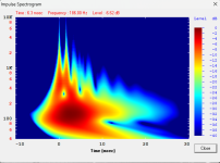
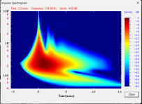
Measured at 1m from horns mouthYou didn't provide a rational explanation, much less any proof of your odd assertions.
vs
2" from Exit, no horn
Both at 3volts. It would seem that the driver is moving into excursion territory that would be causing severe non linearity but the measurements without the Horn the true nature of THD is actually below 1%.
The dampened situation versus the slot remodelNo idea what "situation" you are asking about, but I still prefer a crossover region to be as free of peaks and dips as possible.
vs fixing below with EQ
I'm looking through my measurements, I think the un-horned measurement above is with voicing. Though voltage is 3volts on each but I think there is a low pass and Eqing on the un horned measurement. I can redo the experiments in the future but I think you are getting my drift>? The THD readings in the areas around and below cutoff are skewed.
The voltage and the measurement below is definitely below 3volts and at ~1 meter. This is also the low pass and eqing that is likely on the un-horned measurement.

Below are the THD readings, though taken indoors. 135%thd? That would suggest that the crossover is too low, pushing the diaphragm into areas where non linearity would be an issue for the whole spectrum if those high THD LF were apart of the passband.

With the horn removed, and at a higher voltage (3v), its obvious that the THD measurements above do not represent such gross non linear distortion.

I also realize this is only an issue for myself, or a person trying to use the maximum bandwidth of a horn.
The voltage and the measurement below is definitely below 3volts and at ~1 meter. This is also the low pass and eqing that is likely on the un-horned measurement.
Below are the THD readings, though taken indoors. 135%thd? That would suggest that the crossover is too low, pushing the diaphragm into areas where non linearity would be an issue for the whole spectrum if those high THD LF were apart of the passband.
With the horn removed, and at a higher voltage (3v), its obvious that the THD measurements above do not represent such gross non linear distortion.
I also realize this is only an issue for myself, or a person trying to use the maximum bandwidth of a horn.
- Home
- Loudspeakers
- Multi-Way
- Is it possible to cover the whole spectrum, high SPL, low distortion with a 2-way?