Take a picture, two pairs eyes are sometimes better than one, you have been staring at it for hours maybe fatigue causes you to look past a problem.
Okay, it took a good couple of hours to crack it open (mainly involved very careful removal of silicone sealent) but I'm in!!
Attachments
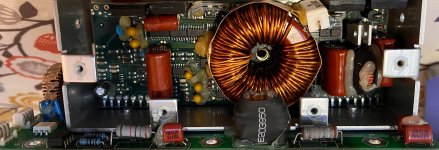
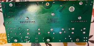
There is obviously a bad 18k resistor in the first picture.
It may be taken out by failure of another component.
It may be taken out by failure of another component.
Last edited by a moderator:
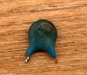
Cap removed from board. It's cracked and heat scored so I decided to snip it off the board rather than desoldering in case I damaged it further (didn't want to lose the marking on it).
It's a 1nF, 1kV ceramic that seems to sit directly between the power board's positive speaker connection (connected to the source and drain of what I presume to be the output FET's of the classD amp)and some internal net (can't trace as it runs on an inner PCB layer).
What I can say is that, having removed it, the amp makes no sound at all. Critically though because it is as dead as a dodo.
As usual, no idea whether the absence of this component is the cause of this new behaviour or whether I've broken something else during disassembly. So, new parts on order and I'll see what happens when I replace the broken cap. This is assuming I can manage to get the new part in, the board is incredibly fragile with loads of minimum width PCB tracks.
I have to say, I'm surprised that the absence of this component causes the amp to fail to start up at all. At only 1nF, I couldn't see it being large enough to be involved in any feedback role. That said, it runs on minimum width tracks so I guess it is unlikely to be involved in any sort of filtering/suppresion role. It also gives me hope that this might fix the issue I've been having, if this cap's role is critical enough to prevent the amp from starting up, I guess a partial connection would be enough to give unpredicatable behaviour.
Wish me luck getting the replacement part in there.....
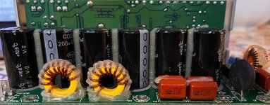
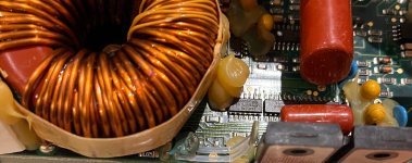
Ohh yes, and a wee family of five tantalum caps that you can see in the attached images on the main amp board. I will try to address these whilst I'm in there. Though, I'll see about fixing the main issue first.
It's a 1nF, 1kV ceramic that seems to sit directly between the power board's positive speaker connection (connected to the source and drain of what I presume to be the output FET's of the classD amp)and some internal net (can't trace as it runs on an inner PCB layer).
What I can say is that, having removed it, the amp makes no sound at all. Critically though because it is as dead as a dodo.
As usual, no idea whether the absence of this component is the cause of this new behaviour or whether I've broken something else during disassembly. So, new parts on order and I'll see what happens when I replace the broken cap. This is assuming I can manage to get the new part in, the board is incredibly fragile with loads of minimum width PCB tracks.
I have to say, I'm surprised that the absence of this component causes the amp to fail to start up at all. At only 1nF, I couldn't see it being large enough to be involved in any feedback role. That said, it runs on minimum width tracks so I guess it is unlikely to be involved in any sort of filtering/suppresion role. It also gives me hope that this might fix the issue I've been having, if this cap's role is critical enough to prevent the amp from starting up, I guess a partial connection would be enough to give unpredicatable behaviour.
Wish me luck getting the replacement part in there.....
Ohh yes, and a wee family of five tantalum caps that you can see in the attached images on the main amp board. I will try to address these whilst I'm in there. Though, I'll see about fixing the main issue first.
Attachments
There is obviously a bad 1k8 resistor in the first picture.
It may be taken out by failure of another component.
Yes, it does look dodgy but that seems to be just the angle of the photo. In reality it tests fine and looks much better than the photo suggests.
Compare to R4, the grey colour turned into white. There must
be an associated problem, check where the connections go.
be an associated problem, check where the connections go.
Yes opening a device and first visually diagnosing and measuring are still the way to go.
That blue ceramic cap is a special 1 kV rated so called "safety" X1/Y1 type best replaced for a similar one by a known good brand so not Aliexpress quality. Preferably with exactly the same pitch. Choosing a 1.5 kV rated type in the same pitch is not a problem.
That blue ceramic cap is a special 1 kV rated so called "safety" X1/Y1 type best replaced for a similar one by a known good brand so not Aliexpress quality. Preferably with exactly the same pitch. Choosing a 1.5 kV rated type in the same pitch is not a problem.
Last edited:
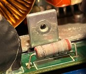
Here's a close up photo. Both resistors show signs of long term heat. Bear in mind, the amp is nearly 20 years old.
Tracing nets on these is not possible unfortunately, they dissapear between the amp assembly and the ground plane. they do not appear to connect to any of the pins that run from the base power board up to the amp board.
I'll put it on the back burner for now and see how the cap replacement works out.
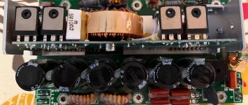
FYI, all power devices IRFP540 measure as they should (or as much as I can tell 'in circuit').
Tracing nets on these is not possible unfortunately, they dissapear between the amp assembly and the ground plane. they do not appear to connect to any of the pins that run from the base power board up to the amp board.
I'll put it on the back burner for now and see how the cap replacement works out.
FYI, all power devices IRFP540 measure as they should (or as much as I can tell 'in circuit').
Yes opening a device and visually diagnosing and measuring are still the way to go.
That blue ceramic cap is a special 1 kV rated so called "safety" X1/Y1 type best replaced for a similar one by a know good brand. Preferably with exactly the same pitch.
https://www.farnell.com/datasheets/5769.pdf
For instance:
DE1E3RA102MN4AP01F
I have a few 2kV ones on order from a good supplier. I'll hopefully have them in a few days.
Obviously, you never know at this point whether you're looking at cause of failure or a result of failure elsewhere but the fact that the minimum width PCB tracks remain unscorched gives me some hope that the cap has not failed as some sort of horrible overcurrent event. I have to bear in mind too that the original failure mode was intermittent in as much as the amp would recover to normal operation after a few minutes.
As long as they're safety types for the same intended purpose all is good.
At first sight part quality is not to write home about in that device. Chinese contract work or Chinese cheap parts. I think I see the famous "Lelon" caps. The brand that once was one of the main offenders in the cap plague.
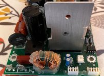
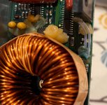
It could be a good idea to run the device and measure the temperature of the large coil/transformer. If it becomes too hot you may have to take some measures to have better heat disposal. A few 6 mm holes away from the coil and EMI radiating stuff creating an air inlet and outlet for instance.
At first sight part quality is not to write home about in that device. Chinese contract work or Chinese cheap parts. I think I see the famous "Lelon" caps. The brand that once was one of the main offenders in the cap plague.
It could be a good idea to run the device and measure the temperature of the large coil/transformer. If it becomes too hot you may have to take some measures to have better heat disposal. A few 6 mm holes away from the coil and EMI radiating stuff creating an air inlet and outlet for instance.
Last edited:
Where is the picture ? The resistors may form op amp supply from a higher voltageHere's a close up photo. Both resistors show signs of long term heat. Bear in mind, the amp is nearly 20 years old.
Tracing nets on these is not possible unfortunately ..
with additional zeners.
As long as they're safety types for the same intended purpose all is good.
At first sight part quality is not to write home about in that device. Chinese contract work or Chinese cheap parts. I think I see the famous "Lelon" caps. The brand that once was one of the main offenders in the cap plague.
It could be a good idea to run the device and measure the temperature of that coil.
Here's the cap I have ordered :
No mention of X1/Y1 or saety cap status but other specs appear a match.
I will definitely check temperatures if and when I am able to coax the amp back into life. For now, as I say, it is completely dead.
Overall, the quality of the PCB and soldering does not lead me to believe this is a great quality product. Still for sale incidentally (albeit with a revised amp) for £1375!!!
Cheers.
Not sure why the picture did not attach. I'll try again.Where is the picture ? The resistors may form op amp supply from a higher voltage
with additional zeners.
Attachments
That is not the right cap as it should be a certified safety type. This one is just as questionable quality as the old one. If the brand doesn't know how to write kV and kHz they seem technically illiterate and I would not trust their product. Probably both AC and DC rated (and in case it gets hot 125 Celsius rated) caps are needed. Since it is in a vibrating environment an enforced version seems no luxury.
Since the device does not work at all without this cap it could be a good idea to forget assumptions and choose parts that will not say goodbye in the next 10 years.
https://search.murata.co.jp/Ceramy/image/img/A01X/G101/ENG/DE1_RA_P01F_E.pdf
Since the device does not work at all without this cap it could be a good idea to forget assumptions and choose parts that will not say goodbye in the next 10 years.
https://search.murata.co.jp/Ceramy/image/img/A01X/G101/ENG/DE1_RA_P01F_E.pdf
Last edited:

They certainly crazy about gluing everything together. Capacitor do not usually dissipate heat and burn unless the plates fused together, it something else heat that tantalum cap. Also that resistor looks dodgy, measure it after being powered a while, could become different value or even open when hot and the end caps moved. Those boards are a nightmare to work on, it is very densely packed and blobs of glue everywhere. I may even suspect a dry joint from contraction and expansion with heat. Furthermore, why is the power transistors on the right discolored and physically damaged did they cook and was removed and replaced. Is this a sentimentally valuable amp, why did you want to repair it? Would it not be cheaper to just replace it?
Post #33, that is the third post before yours. 1375 UK Pound or 31000 Rand. Pretty good reason to repair to many.
Replace for higher power rated so somewhat larger ones (ones that fit) and reflow at both sides of the PCB with 60/40. Check all power parts soldering as soldering is so so.Not sure why the picture did not attach. I'll try again.
Last edited:
The resistor seemed to get hot to the extent that the solder drew out the through hole plate by the looks of it. Pull on the wires and see if it dislodges.Not sure why the picture did not attach. I'll try again.
The resistor seemed to get hot to the extent that the solder drew out the through hole plate by the looks of it. Pull on the wires and see if it dislodges.
No, that's just how badly assembled this thing is 🙄. Most components are similarly attached.
The resistor is firmly in place and well soldered on the back side of the board.
@as_audio, you have a good eye. The resistors do indeed form part of a +/-18V with a pair of zeners (supply directly dropped from +/-150V).
Just fired it up again and found that, despite lack of audio output, the power supplies are all active. The resistors in question are mildy warm after a couple of minutes of being switched on. Similarly, the torroid and output FETs all sit at a temp that is just discernably warm to touch.
Do you reply at all to suggestions? Or am I wasting my time?
BTW "The resistors do indeed form part of a +/-18V with a pair of zeners (supply directly dropped from +/-150V)." is just crazy. Dividing in 2 resistors will have thermal benefits.
Temperature measurements always under load (not idle) and after at least 30 minutes.
BTW "The resistors do indeed form part of a +/-18V with a pair of zeners (supply directly dropped from +/-150V)." is just crazy. Dividing in 2 resistors will have thermal benefits.
Temperature measurements always under load (not idle) and after at least 30 minutes.
Last edited:
- Home
- Design & Build
- Parts
- How do tantalum caps fail in AC coupling applications?