Hi guys,
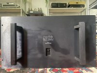
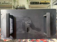
Bought an Levinson ML3 amp for sentimental reasons I think. I had a schematic for it but lost it in my latest move to another house.
Mailed with the original designer Tom Colangelo in 2003 about a conversion from 120V to 220V. He told me that he lost all his paperwork about these old MLAS models in 1989 due to tornado. Due to the age of 40 years of this amp and it's completely original it could be a candidate for some maintenance.
Maybe somebody has the service manual of schematics of the ML3. Any help is welcome of course.
This one has been converted to 220 AC already.
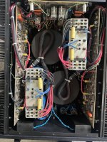
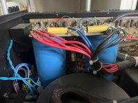
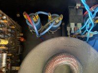
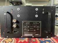


Last edited:
Great you have them all three!
The one with a 18000uf silver Callins filtercaps.
The one with the 33000uf Spragues and the one with the 36000uf Spragues.
Single and double fuseholders.
The ones with and without dampingswitches.
Ones with the added four smaller blue Sprague filtercaps for the predriverstage.
On my lost schematics MLAS added the Series I to III.
Do you have any info for me maybe?
Just another question.
The MLAS specified emitter voltage over the .56 Ohm emitterresistors is 47mV
With 10 pair powertransistors per channel with a load of 4 Ohm I get 5.6 Watts of Class A per channel.
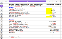
The ML-3 has huge heatsinks (although rather short fins) and I wonder if this biassetting can be safely increased with a maximum of 45 degrees Celcius value roomtemperature 20 degrees. Or are their other parameters to consider?
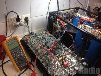
The MLAS specified emitter voltage over the .56 Ohm emitterresistors is 47mV
With 10 pair powertransistors per channel with a load of 4 Ohm I get 5.6 Watts of Class A per channel.

The ML-3 has huge heatsinks (although rather short fins) and I wonder if this biassetting can be safely increased with a maximum of 45 degrees Celcius value roomtemperature 20 degrees. Or are their other parameters to consider?

I wouldn't touch the bias with 90v rails. Very easy to hit dangerous territories, and for what?
You can always test at small increments and see how it affects the sink temperature.
You can always test at small increments and see how it affects the sink temperature.
I wouldn't touch the bias with 90v rails. Very easy to hit dangerous territories, and for what?
I read a technical paper from Nelson Pass where he stated and showed that Class A enrichment lowers all kind of distortion.
It was called 'Leaving Class A' and he stated:
"Higher bias doesn’t just move the Class A transition to higher ground – it has a profound influence on the amplifier at all power levels. It lowers the distortion at low levels as well as high levels, as seen in the distortion vs power curves for an amplifier with the bias set at different levels.¨
Then he showed this graph:
So I thought what the heck lets give it a try.
I will be very careful of course. Have experience with the one turn biastrimmers in my Threshold SA/1.
Will first check the bias after the unit heats up with an hour and then check for the current biassetting with several emitterresistors and adjust it if necessary.
I will use an energymeter to check the AC intake
Then I will check the temperature and when the heatsinks permit it I can slowly raise the bias while still carefully monitor the AC intake of course.
Easy does it and patience are the keys. 😎
Thanks for the supportive remark. I luckily also the have Threshold 'Standard Amplifier Bias Procedure' as a reference.
Would a heatsink temperature of 25 degrees Celcius increase over the surrounding temperature be a good reference point you think?
Any other considerations?
Okay that would be around 48 degrees Celcius I believe.Being that it's Class A, I would go with the warmest temperature you can leave your hands on.
Thank you very much for the advice.
To be sure I just check if you didn't confuse this stereo ML3 with the monaural Levinson ML2 which you are very much aquinted with.Being that it's Class A, I would go with the warmest temperature you can leave your hands on.

Robert and group,
Were you able to get a schematic for your ML-3 from RM? I have a ML-3 that I purchased and was told it working. It was shipped to me heavily packaged and boxed up but still suffered some damage in shipment. All the large filter caps had come loose from their bottom held clamps and left channel had some broken small caps on the circuit board for the filter caps. I remounted everything and put 2 new caps and left side will not turn on. I did not see anything else broken or disconnected. My model has no switch and single fuse. I need a schematic for this beast. Its serial number is 0223 if this helps. It is in Lake Wales right now I and I recall had 36000 Spragues. If I cant figure out what else is wrong is there anyone good in SW Florida for repairs?
Tim Naples FL
That's a real bummer.
I live in Europe an do not know any repairfacilities in FL.
Luckily the ML3 is very service friendly in contrast with its successor the No. 23.
Any skilled technician can solve this for you I'm sure.
I live in Europe an do not know any repairfacilities in FL.
Luckily the ML3 is very service friendly in contrast with its successor the No. 23.
Any skilled technician can solve this for you I'm sure.
Thanks Robert and sorry for the slow response as I was traveling. Were you able to find schematics for your ML-3? For service here in Naples is tough. We are in a disposable envirnment and not too many electronics repair Techs around this neck of the woods and shipping that AMP is as much as repair I am guessing. I still think something is dislodged or physically broken and I think with a proper schematic I could probably tackle it. I just odnt want the monster to sit on a bench in a million pieces. I used to repair TV back in the day but since have moved on to diferent trade. Glad I did, Id be broke.
No, did not get any schematics.
Don't really need them either for the bias and DCO.
You can maybe ask Paul Jayson of Viola Labs, he worked together with the late Tom Colangelo ar MLAS, Cello and Viola Labs till 2007.
Don't really need them either for the bias and DCO.
You can maybe ask Paul Jayson of Viola Labs, he worked together with the late Tom Colangelo ar MLAS, Cello and Viola Labs till 2007.
Main filtercaps in the ML3 are 40 years old. Luckily Digikey had just four drop-in replacements in stock.
The reference is a 500cc can of (awful) German beer.
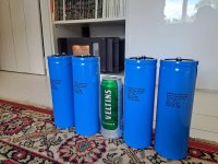
With 90 Volts railvoltage it will be 810 Joules of energy per channel like the big tube amps from Audio Research.
Of course I will replace the decoupling caps for the voltage stages also as some small axial and radial caps on different PCB's.
I've seen techs (ten times more educated in the electronic field than I am) that replace these filtercaps with the same capacitance rating as the original value. I never got a good explanation why an increase in capacitance wouldn´t be possible with the same voltage rating of course as the original filtercaps. Only once something about the extra stress for the bridge rectifiers. Or (soft) startup circuit powerresistors/relais?
I've done so with Levinson ML2´s, Threshold Stasis 3, S/500, S/1000 and SA/1's without any failures. Maybe I was just lucky but I'm still curious.
The reference is a 500cc can of (awful) German beer.

With 90 Volts railvoltage it will be 810 Joules of energy per channel like the big tube amps from Audio Research.
Of course I will replace the decoupling caps for the voltage stages also as some small axial and radial caps on different PCB's.
I've seen techs (ten times more educated in the electronic field than I am) that replace these filtercaps with the same capacitance rating as the original value. I never got a good explanation why an increase in capacitance wouldn´t be possible with the same voltage rating of course as the original filtercaps. Only once something about the extra stress for the bridge rectifiers. Or (soft) startup circuit powerresistors/relais?
I've done so with Levinson ML2´s, Threshold Stasis 3, S/500, S/1000 and SA/1's without any failures. Maybe I was just lucky but I'm still curious.
Last edited:
- Home
- Amplifiers
- Solid State
- Levinson ML3, bought an old love back