I built a modded Marshall 2203 guitar amp a few years back and ended up needing to do some prototyping on it to get it right.
Basically its the same schematic but with different B+ voltages and using 807 tubes (based on the advice of an old fella who has now since passed away.)
Looking back now I would have just built a pure replica with EL34 tubes, but hey this thing is unique!
My main concerns are around Bias voltages, plate voltages on preamp tubes and poor presence control.
The amplifier seems to sound OK, but I felt it did not put out as much power on the low sensitive input as the high did.
Not too sure if this is normal for this design or not, but its still pretty damn loud when cranked up full, from memory im getting closer to 200W on the high sensitivity input when overdriven.
This thing is a beast for sure.
So the mods are as follows:
B+ 400V
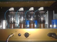
807 output tubes
12AT7 phase inverter
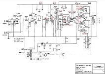
everything before the phase inverter is the same as the marshall design, I have highlighted my changes in red on the schematic.
When taking measurements, i got the feeling that the plate voltages on the preamp tubes might be high, the old guy also told me to change the resistor values on the power supply at the top (highlighted in red) changing the original 10K value didnt seem to reduce the plate voltages much, so i just left at 4.7K and 1K respectively.
Voltages measure as follows:
V1A anode to ground 280V
V1B anode to ground 335V
V2A cathode to ground 1.5V, anode to ground 191V
V2B cathode to ground 190V, anode to ground 383V, across anode to cathode 189V
Phase inverter, anode to ground 265V, across anode and cathode 168V
Do any of these voltages look too high? 335V on V1B seemed a bit too high to me.
As far as presence control goes, even the original marshalls had poor response and little to no difference in sound is observed, I dropped it down to 4.7K from 100K and it makes more of a difference to the negative feedback received, the difference in the phase inverter may also have a role to play.
As far as bias voltage goes, i think ive got it sitting around -50V from memory, Im not sure ive got this right, as a rule 10% of plate voltage should be applied, I think i went by ear mostly and left it where I felt it sounded right, but I should revisit this.
Any other feedback is appreciated, largely the amp seems to run sweet, but I just want to tidy this thing up and order some new resistors to replace the ones ive tacked on while prototyping it.
See schematic attached, modded values are marked in red.
Basically its the same schematic but with different B+ voltages and using 807 tubes (based on the advice of an old fella who has now since passed away.)
Looking back now I would have just built a pure replica with EL34 tubes, but hey this thing is unique!
My main concerns are around Bias voltages, plate voltages on preamp tubes and poor presence control.
The amplifier seems to sound OK, but I felt it did not put out as much power on the low sensitive input as the high did.
Not too sure if this is normal for this design or not, but its still pretty damn loud when cranked up full, from memory im getting closer to 200W on the high sensitivity input when overdriven.
This thing is a beast for sure.
So the mods are as follows:
B+ 400V
807 output tubes
12AT7 phase inverter
everything before the phase inverter is the same as the marshall design, I have highlighted my changes in red on the schematic.
When taking measurements, i got the feeling that the plate voltages on the preamp tubes might be high, the old guy also told me to change the resistor values on the power supply at the top (highlighted in red) changing the original 10K value didnt seem to reduce the plate voltages much, so i just left at 4.7K and 1K respectively.
Voltages measure as follows:
V1A anode to ground 280V
V1B anode to ground 335V
V2A cathode to ground 1.5V, anode to ground 191V
V2B cathode to ground 190V, anode to ground 383V, across anode to cathode 189V
Phase inverter, anode to ground 265V, across anode and cathode 168V
Do any of these voltages look too high? 335V on V1B seemed a bit too high to me.
As far as presence control goes, even the original marshalls had poor response and little to no difference in sound is observed, I dropped it down to 4.7K from 100K and it makes more of a difference to the negative feedback received, the difference in the phase inverter may also have a role to play.
As far as bias voltage goes, i think ive got it sitting around -50V from memory, Im not sure ive got this right, as a rule 10% of plate voltage should be applied, I think i went by ear mostly and left it where I felt it sounded right, but I should revisit this.
Any other feedback is appreciated, largely the amp seems to run sweet, but I just want to tidy this thing up and order some new resistors to replace the ones ive tacked on while prototyping it.
See schematic attached, modded values are marked in red.
Attachments
The right place for this thread is the instrument amplification area of the forum.
With 807 at 400V on both plate and screens you should be able to get around 100 dirtish Watts from a quad in class AB1 biasing around -35V on a 5k Raa loadline, swinging around 70Vpp on output tube's grids. What do you use exactly?
PS
There's no rule about 10% of the B+ voltage for biasing.
With 807 at 400V on both plate and screens you should be able to get around 100 dirtish Watts from a quad in class AB1 biasing around -35V on a 5k Raa loadline, swinging around 70Vpp on output tube's grids. What do you use exactly?
PS
There's no rule about 10% of the B+ voltage for biasing.

Guitar amps are known to abuse output tubes.
That amp has already the 807 with screens running at 400V (except when the voltage drops during peaks, as most guitar amps do per design).
That amp has already the 807 with screens running at 400V (except when the voltage drops during peaks, as most guitar amps do per design).
I see this thread has since been moved there, these marshall amps are designed to be run in class AB as far as im aware.The right place for this thread is the instrument amplification area of the forum.
With 807 at 400V on both plate and screens you should be able to get around 100 dirtish Watts from a quad in class AB1 biasing around -35V on a 5k Raa loadline, swinging around 70Vpp on output tube's grids. What do you use exactly?
PS
There's no rule about 10% of the B+ voltage for biasing.
I use a quad cabinet which is rated at 320W from memory, using four celestion G12 speakers.
Voltage was about 50V that I had it set to, I thought i had it originally closer to 40V but this was 10 years ago, I now since have a different multimeter that is probably more accurate than the cheap one I had at the time, perhaps other components have drifted in their reading over that time too.
Now I dont know where the idea of using 10% of the B+ for setting bias comes from, but the old fella who helped me at the time told me its a guide for getting it in the rough spot.
Ive been told by several HAM operators that the grids on these tubes can safely handle 400V and that they used to push these things hard and they lasted forever, perhaps it shortens the life, but I think there is a bit more to it. This thing does not get a ton of use anyway but I can testify that the 807 is a pretty rugged tube.400V on the screen grids is a bit too high for 807s, all datasheets I've seen states 300V max. 400V probably works for a while but for how long? A quad of good 807s whould last a long time ina 100W amp if the ratings are respected, they are workhorses.
Ive also heard that it depends on the operation of the tube, I dont think class A is as forgiving for example.

807 shouldn't see more than 300v on the screens plates when the plates are seeing 600v. Lower the plate voltage and screen can dissipate more. I saw somewhere that U/L was invented after 807, and there was some kind of push to re-do the 807 datasheet with an U/L spec at 400v ma for plate and screen. I dunno. Good thing they're cheap.
Well the plates on this are only at 400v and should be kinder.
I haven't had issues over the 12 years I've had it, and they are going strong.
My main concern right now is the voltages on the preamp tubes.
I haven't had issues over the 12 years I've had it, and they are going strong.
My main concern right now is the voltages on the preamp tubes.
In the original 2203 it is 10k or 22k (depends on the versions and voltages), for a 12ax7 (actually three after it).
That causes 60 to 120V drop across it approximately. With two 12ax7 and a 12at7 you drop more or less the same with lower dropping resistors (approximately 1/4th of the original value).
I usually run 2203 kind of circuit at 250V for V1 and 280V for V2 (on the psu node).
That causes 60 to 120V drop across it approximately. With two 12ax7 and a 12at7 you drop more or less the same with lower dropping resistors (approximately 1/4th of the original value).
I usually run 2203 kind of circuit at 250V for V1 and 280V for V2 (on the psu node).
Both the 12AT7 PI and the 807 power tubes result in considerably less power amp forward gain than the original circuit.
Consequently the difference between power amp gain with and without global NFB, which determines the available presence boost, is small.
Another effect is lower power amp and thus total amp sensitivity.
Lowering the NFB series resistor to 4.7k should give a little more presence, but reduces sensitivity even more.
Did you measure output power?
All 807's are not created equal. The original 808 was simply a 6L6G stuffed into a 5 pin base with a plate cap and some RF shielding around the bottom of the lower mica. As time passed and the 6L6 evolved the tube manufacturers simply stuffed the glass with whatever 6L6 variant they were making at the time. Later tubes got later guts. Over 20 years ago I got over 100,000 tubes for free in exchange for helping the cleanup of a derelict warehouse where they were stored. Vagrants, homeless, druggies, and lots pf pigeons took turns trashing the place and smashing tubes by the thousands. It hurts to find probably 100 833As all broken along with some 211s, 845s, 807s and 1625s. The latest tube I found in the place was from the early 60's and this was late 90's.
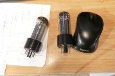
I found lots of things called 807 or 6BG6GA (a 6L6 based TV sweep tube). There were some 807s and 6BG6s with 6L6GC and 7027 guts inside! The width of the fins on the plate is the giveaway to the vintage and lineage of the tube. It's hard to say how wide the plate fins are in your pictures, but if they are similar to what's in the SND pictures they will live long and prosper.
SND tube sales have been selling the 6BG6GA tube stuffed with 7027A guts for some time. I got some when they were under $5 each!
http://www.vacuumtubes.com/6BG6.html
In the oddball 6L6 type tube department, here you will find some black plate RCA 6L6 guts inside a 6V6GT sized envelope. The plate wings are the old 19 watt size and they were clipped a bit to fit the glass. Beat them hard and they will melt!
Attachments
I had rolled a few tubes some time back but never checked the measurements.Have you swapped any other valves in the preamp sockets? I'd go for the 10k dropping resistor in the PS, see what happens.
Im pretty sure at the time i tested the tube that it was fairly balanced, but it was not my tester and ive since got myself a calibrated tester, so might be a good idea to revisit this.
Im pretty sure this schematic specifies 10K (four of the things in total, 1st stage is two in series so perhaps thats the 22k you are referring to? Ive only got 1K there presently)In the original 2203 it is 10k or 22k (depends on the versions and voltages), for a 12ax7 (actually three after it).
That causes 60 to 120V drop across it approximately. With two 12ax7 and a 12at7 you drop more or less the same with lower dropping resistors (approximately 1/4th of the original value).
I usually run 2203 kind of circuit at 250V for V1 and 280V for V2 (on the psu node).
voltage on the first triode stage seems OK, but the second stage is rather high at 335V. V2 seems OK when measured across cathode and anode, which is essentially what the valve sees rather than measuring from the anode to the chassis?
Phase inverter measurements on the 12at7 dont seem to much concern to me, I wonder if the last dropping resistor could benefit with 22K?
There are a number of variants, ive also got some ceramic based types and some with smoked glass.All 807's are not created equal. The original 808 was simply a 6L6G stuffed into a 5 pin base with a plate cap and some RF shielding around the bottom of the lower mica. As time passed and the 6L6 evolved the tube manufacturers simply stuffed the glass with whatever 6L6 variant they were making at the time. Later tubes got later guts. Over 20 years ago I got over 100,000 tubes for free in exchange for helping the cleanup of a derelict warehouse where they were stored. Vagrants, homeless, druggies, and lots pf pigeons took turns trashing the place and smashing tubes by the thousands. It hurts to find probably 100 833As all broken along with some 211s, 845s, 807s and 1625s. The latest tube I found in the place was from the early 60's and this was late 90's.
I found lots of things called 807 or 6BG6GA (a 6L6 based TV sweep tube). There were some 807s and 6BG6s with 6L6GC and 7027 guts inside! The width of the fins on the plate is the giveaway to the vintage and lineage of the tube. It's hard to say how wide the plate fins are in your pictures, but if they are similar to what's in the SND pictures they will live long and prosper.
SND tube sales have been selling the 6BG6GA tube stuffed with 7027A guts for some time. I got some when they were under $5 each!
http://www.vacuumtubes.com/6BG6.html
There is a variant with a ceramic base called an ATS25, but not all marked ATS25 have the same plate design.
I have some with a round plate, and I think these were the more rugged military variant.
Yes i measured the RMS output which from memory averaged around 160w, Higher notes were even reaching 190W and lower notes were around 120W which is to be expected.Both the 12AT7 PI and the 807 power tubes result in considerably less power amp forward gain than the original circuit.
Consequently the difference between power amp gain with and without global NFB, which determines the available presence boost, is small.
Another effect is lower power amp and thus total amp sensitivity.
Lowering the NFB series resistor to 4.7k should give a little more presence, but reduces sensitivity even more.
Did you measure output power?
The only reason I went with the 12AT7 was the old guy recommend i use it and drew me the schematic which he reckons would drive them well.
I would have thought it would have been better with the 12AX7 as the marshall used, but he said that the 12AT7 will drive the tubes with more current even if its less gain.
I did find that dropping the NFB series resistor to 4.7k made a huge difference and thats what ive been using, but your right, it affects sensitivity, not sure what workaround I can do around this.
These numbers look high with a plate voltage of only 400V.Yes i measured the RMS output which from memory averaged around 160w, Higher notes were even reaching 190W and lower notes were around 120W which is to be expected.
Did you measure before clipping?
I'd expect less than 80W clean.
Last edited:
The calculator shows an output of 28W per pair. (Not clear what Raa you used).Here's what I get from it's results, 30W per tube I'm assuming at 45v bias.
Sounds about right to me.
So 56W with 4 tubes.
But only if B+ wouldn't sag at full output.
From memory it was a clean sine wave on the scope, perhaps i did my calculations wrong.These numbers look high with a plate voltage of only 400V.
Did you measure before clipping?
I'd expect less than 80W clean.
I measured the voltage across the dummy load, then squared and divided by the loads impedance which gave me the RMS watts.
This was the formula i used:
P = V²/R = V²/8Ω
probably worth checking this again
- Home
- Live Sound
- Instruments and Amps
- Thoughts on my modded Marshall 2203 build?