Thanks Ben, I was struck by the fact clipping in the CS never wants to arrive.
When the temperature drop a bit I try to convert my CD to CS.
When the temperature drop a bit I try to convert my CD to CS.
It sounds delightful to... my eyes! 😀dunno is that age or what, but in last time I'm often forgetting to take phone (cam) with me in workshop, so again no proof is in da pooding pics; meaning - No Porn, No Glory for Mighty ZM, but whatever
at least these few pics I have from assembling pcbs, few days ago
will take few pics of small version tomorrow and post
Big budget needed but soooo interesting! 🍻
There must be a graphic that conveys Choked Singing Bush....
😉
well, that missing, as illustration of my obvious incompetence to wrap idea in full success, that logically being result of lack of inspiration
anyhow, after the fact, this is best I can do :
now, take it as Schlagwort for reading some funny facts
https://www.eightieskids.com/facts-about-three-amigos-that-you-probably-never-knew/
My CD is an ultra simple choke loaded common drain. It's a copying and pasting of Ben's Fokin with a 30 V PSU. Bias is stable. Turning it into a CS is simple. Just reverse the connections of the drain and the source. If the bias is still stable, I'm fine. If the bias escapes there is the Choked Singing Bush.
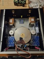
Evening ZM, I've been pulling together my bits for the Choked Singing Bush and I should have a bit of time where I can build it soon. I wanted to double check my thinking on the layout so I've attached a picture of what I had in mind. Do you think it works well? I'm wondering if the big Lundahl chokes down by the signal input might be an issue....
The power supply is the 2 toroids with single 24v secondaries (mounted one on top of each other). As it's single not dual secondaries, I assume that the norm would be to wire one down each side of each HA cap bank board? Is that correct?
I ended up with 4 of the Hammond 159ZJs, so I was wondering, can I run the cap bank C-L-C-R C-L-C on each board, so run C-L-C down one side, wire a resistor and C-L-C back up the other? If this is daft, pointless, unnecessary I can run normal C-L-C for both secondaries on one board but I bought chokes and caps to populate 2 of them. Oh then motor run caps at the end.
Bit's that might not be immediately obvious, the blue board in the top middle is a balanced to SE convertor, this will be raised to the same height as the XLR connectors on standoffs, the power then going in underneath it (where there will be a soft start board mounted at the bottom, below the XLR - SE board. I was thinking that the wires from XLR would then come immediately in to this board and stay further away from the chokes
And then at the front middle is a small board for running a couple of VU meters.
What do you think? Does it seem a reasonable layout? Does the PSU chokes idea make any sense?
This beast weighs an incredible amount by the way....
Attachments

move toroid all the way to the front plate, then stash rest as it falls logically
route mains wires beneath base plate ( lip up!)
I don't think that signal chokes will do harm in vicinity to inputs - that's no gain circuit and no NFB, so hardly suspect as most more active circuits are
regarding chokes - if you already have 4pcs, make positive rail CLC and also negative rail CLC, bingo
if you have any dilemma how to accommodate my dual rails pcbs for that, just buzz
Ah great, thanks for that and good to know on the chokes, so I'll aim for a layout more like this then.
I'll have a bit more of a look at the PCBs and check if I can see it, I drew a blank last time but now I know it's there.... I'll give you a shout if I have any trouble working it out.
Hopefully soldering soon!
I'll have a bit more of a look at the PCBs and check if I can see it, I drew a blank last time but now I know it's there.... I'll give you a shout if I have any trouble working it out.
Hopefully soldering soon!
Attachments


Ah, ZM, I've had a look a few times and can't work it out with it for the PCBs, I figure I'm being an idiot..... Do you mind letting me know how to do it?regarding chokes - if you already have 4pcs, make positive rail CLC and also negative rail CLC, bingo
if you have any dilemma how to accommodate my dual rails pcbs for that, just buzz
remind me how many of my Cap Bank pcbs you have
worth saying also how many caps and which ones you have on disposal
worth saying also how many caps and which ones you have on disposal
I've got 4 of the cap bank pcbs and with caps, 8 of the shiny 33,000uf Mundorf Mlytic AGs
Edit - not that I'm assuming I need 4 cap banks here, I just have spares...
Edit - not that I'm assuming I need 4 cap banks here, I just have spares...
see, some work involved
it easy and simple making it single rail, with solid GND side, and CRC(CLC) in positive - just matter of rotating lower caps , and appropriate wiring in input side and output side
but, making negative side split, to introduce R/L in a middle....... time for exacto knife, metal ruler ( as guide for knife), 1.5mm or 2mm drill ....... and some patience
observe flipped polarity of lower caps
also observe - on left side we have Pos and Neg rail; point is - we have established B+ and GND at right side, only after each particular choke
everything else written
buzz if needed, to make it fully clear
Last edited:
Brilliant, thanks for that, I had the thought it might need bridge wires but got nowhere near it.
Out of extra caution, it's also bridge wires to tie the top and bottom positive rails on the in side and then the same on the outside which is then passed through choke 1?
Out of extra caution, it's also bridge wires to tie the top and bottom positive rails on the in side and then the same on the outside which is then passed through choke 1?
Hi Bob, I haven't done so well with it yet, it was a busy year and I got very distracted. I did get as far as pretty much putting together the power supply for it before Christmas though.
It is out on the table for when I get back home as the project I want to get finished. No problem, I will put an update in here and as when it's done and let you know a bit more👍
It is out on the table for when I get back home as the project I want to get finished. No problem, I will put an update in here and as when it's done and let you know a bit more👍
- Home
- Amplifiers
- Pass Labs
- Choked Singing Bush ..... special one for Purists and Masochists