There are many descriptions of the distinction between passive and active equalization RIAA network - e. g.
https://www.tubecad.com/articles_2002/RIAA_Preamps_Part_1/RIAA_Preamps_Part_1.pdf
Passive RIAA means a low pass network between two line stages and active RIAA means a frequency dependent network in the NFB loop.
But there are two different circuit topologies for phono stages with using active RIAA network:
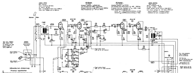
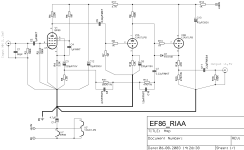
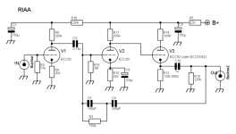
1) RIAA network loop is located within two gain stages (non inverted mode) and sometimes one buffer stage - go to image No 1-3
2) RIAA network loop is located within only one gain stage (inverted mode) and mostly one buffer stage - go to image No 4-6 from the attached files.
But I don't find any details concerning the pros and cons of both circuit topologies. At first glance, the different open loop gain factors come to mind.
Maybe there is already an old and closed thread to this subject here on diyaudio.
Thank you very much for any advice.
https://www.tubecad.com/articles_2002/RIAA_Preamps_Part_1/RIAA_Preamps_Part_1.pdf
Passive RIAA means a low pass network between two line stages and active RIAA means a frequency dependent network in the NFB loop.
But there are two different circuit topologies for phono stages with using active RIAA network:
1) RIAA network loop is located within two gain stages (non inverted mode) and sometimes one buffer stage - go to image No 1-3
2) RIAA network loop is located within only one gain stage (inverted mode) and mostly one buffer stage - go to image No 4-6 from the attached files.
But I don't find any details concerning the pros and cons of both circuit topologies. At first glance, the different open loop gain factors come to mind.
Maybe there is already an old and closed thread to this subject here on diyaudio.
Thank you very much for any advice.
Attachments
-
 active RIAA two gain stages.gif4.3 KB · Views: 346
 -
 active RIAA two gain stages - emt-139.png208.6 KB · Views: 357
 -
 active RIAA two gain stages EF86.png72.8 KB · Views: 341
 -
 active RIAA one gain stage-II.png17.6 KB · Views: 354
 -
 active RIAA one gain stage.jpg91 KB · Views: 339
 -
 active RIAA one gain stage - ear834p.jpg68.9 KB · Views: 331
I would recommend for the anode follower designs (images 4-6) to include a "build-out" resistor in series between first stage anode and the summing junction at second stage grid. It should be significantly large compared to first stage anode resistance, which therefor also makes the RIAA network higher impedance for easier driving.
Image 5 cannot work as drawn because the transistor is biased off. You might try an nJFET in that location.
All good fortune,
Chris
Image 5 cannot work as drawn because the transistor is biased off. You might try an nJFET in that location.
All good fortune,
Chris

My take on this after having tried dozens of phono stage designs is series feedback tended to make records sound noisier than shunt feedback and both active feedback topologies behaved this way more than passive designs.
Passive designs need to have a very quiet 2nd stage as it isn't being helped by the EQ network WRT the hiss component whereas active designs tend to reduce this noise if the FB is overall from the output.
I think many commercial design use active to mitigate somewhat from having to select valves so ongoing in the field support can be minimal. Just an idea.
In the end I preferred passive designs BUT ....
I don't use "typical valves" like the ECC8* and many others that fall into this camp. Sure you can make a pleasant sounding design and there are many out there.
I believe in high gain, low Z to drive the EQ and relatively, a lowish Z EQ (say 15 to 20k series R). Not common in many designs with 100 to 300k series resistor.
Another belief is you won't get an accurate end result unless you model it in SPICE or similar. There are just too many variables to use any form of calculator I've seen.
Cheers,
Stephen
The second category is just EAR834 with more or less "upgrades" vs the rest of the world zillion of models 😀 . Like there are cascode , SRPP and other RIAA designs .
So if the title would be more specific maybe many would share the experience .
Is EAR834 superior to a clasic RIAA ?
So if the title would be more specific maybe many would share the experience .
Is EAR834 superior to a clasic RIAA ?
Last edited:
Your second group has only local feedback around the first stage, so the first stage isn't linearized much by feedback. Then again, it only handles relatively small signals.
The inverting configuration doesn't have the issue that the gain (theoretically, if the active part had infinite gain and bandwidth) approaches 1 instead of 0 for high frequencies, like in a noninverting configuration. That's only a small difference at audio frequencies, but still.
With AC heater supply, in your second group, you could AC short the cathode of the first stage to ground, reducing hum due to heater to cathode coupling. The first stage then works completely open loop.
Miller effect is not an issue with any of the configurations you have shown, at least not in first approximation. It is an issue in my variant of group 2, which you can find here: https://www.diyaudio.com/community/threads/phono-pre-amp-build-recommendations.355775/post-6237480 and https://www.diyaudio.com/community/threads/phono-pre-amp-build-recommendations.355775/post-6239890
Last edited:
Miller is definitively much worse when the first stage is not in the negative feedback loop , like in a passive RIAA
You can live with it or not ...
I'm not sure how the tube internal resistance will change with age , since is part of the feedback loop and RIAA curve
You can live with it or not ...
I'm not sure how the tube internal resistance will change with age , since is part of the feedback loop and RIAA curve
Last edited:
Indeed, but in all of tiefbassuebertr's configurations, the first valve is either in a feedback loop or has its anode AC coupled to a virtual ground (unlike my variant).
Designs with passive RIAA equalization usually have a resistor between the anode of the first valve and the RIAA correction network. Does anyone understand why? Without it, the Miller effect would be much smaller at the frequencies where it matters.
As far as I know, the mu of a triode is mainly determined by the location and dimensions of the electrodes, so the internal resistance should go up as the transconductance goes down.
The series R is part of the EQ network.Designs with passive RIAA equalization usually have a resistor between the anode of the first valve and the RIAA correction network. Does anyone understand why? Without it, the Miller effect would be much smaller at the frequencies where it matters.
As the EQ is a cut to HF, why does Miller matter if it can be part of the EQ?
Miller C seen by the phono cartridge varies with first stage gain, so with cathode grounded varies with anode loading. This argues for a more direct connection from anode of first stage to internal lossy ("passive") RIAA network or anode follower summing junction, but triode first stage linearity argues for lightest possible loading. How to choose?
One could argue for a pentode (or cascoded triodes) first stage, with anode follower second stage. Not fashionable, but checks all the boxes, and often lower distortion (at low signal levels). If worried about partition noise, we could adopt Blohbaum's G2 cascode from Vol. 0. But an anode follower second stage with RIAA wrapped around it is tough to beat.
Phono equalizers = Big fun,
Chris
I think so 😀Phono equalizers = Big fun
I'm all for hi gm pentode 1st stage. Good drive, high gain, low Miller and given all that, low noise.
So many choices.
Sorry; an anode follower is what C. P. Boegli called your second stage back in the early 1960s. Today, in opamp terms we would say an inverting stage with input summing junction. but some folk (not you, of course) might have difficulty stretching to that from a plain brown garden variety common cathode stage. Works the same but without the infinite open loop gain.
Boegli proposed using them everywhere in preamps, even with a pot for volume control in the feedback path - very advanced in his day. Turns out to not really work for the first stage of a phono equalizer, but was still used that way in lots of proposed circuits. A Baxandall tone control is an anode follower. Let's bring the term back! since we don't have another in vacuum valve circles.
Much thanks, as always,
Chris
Last edited:
Thanks for the explanation!
I don't understand how a cascode stage or a pentode could solve the distortion issue, if a triode common-cathode stage with low load resistance would distort too much. The bottom triode in a cascode stage sees a load resistance of 1/gm of the upper triode, so it is working into a very low load. You don' t get the distortion cancellation between the transconductance and internal resistance of a single triode with high load resistance then.
I don't understand how a cascode stage or a pentode could solve the distortion issue, if a triode common-cathode stage with low load resistance would distort too much. The bottom triode in a cascode stage sees a load resistance of 1/gm of the upper triode, so it is working into a very low load. You don' t get the distortion cancellation between the transconductance and internal resistance of a single triode with high load resistance then.
The series R is part of the EQ network.
In principle, you could redesign the equalization network to use the output resistance of the first stage as its first resistor. I think there are several problems with that:
1. When the resistor from the anode to the supply is large, the output resistance of the first stage is largely determined by the internal resistance of the triode, which is inaccurate. The first cut-off frequency of the RIAA correction then also gets inaccurate when there is no resistor between the first stage and the passive RIAA equalization network.
2. When the resistor from the anode to the supply is small, you get Chris's distortion problem and the gain at low frequencies may become insufficient, so you need another gain stage somewhere.
As the EQ is a cut to HF, why does Miller matter if it can be part of the EQ?
It loads the cartridge. Some cartridges are meant for pretty large load capacitances, others are not.
@Stephen R, @Chris Hornbeck and @Depanatoru, thanks, I think I understand it now!
Last edited:
You're right of course. I shouldn't have included cascodes. So, for an input stage with lowest possible Miller C the choice is narrowed to pentodes (as Stephen argues, not a bad choice) or series feedback. Since almost all phono cartridges are floating (not Decca's, but) if we were willing to apply feedback to the "bottom" of the cartridge we could put first stage cathode at signal ground. We could even apply some battery bias there and bolt the cathodes directly to signal ground.
I've used just the battery bias part (floating both turntable channels' hot and ground up by -1.56VDC, common battery supply) for 12AX7 two stage phono, first stage wide open, second stage anode follower with RIAA, and almost got away with AC heaters. Good enough for me when using very low Z cartridges like my beloved but now all deceased Denon DL160. Miller C, Schmiller C, didn't matter to me.
Now need a phono equalizer for a gifted Shure Ultra500 (like a Type V) so I'm thinking about input C. A single OPA2134 would do the deed, but what fun is that?
All good fortune,
Chris
This is where a pentode is advantageous for this type of EQ like the Trafomatic circuit. Pentode plate Z is high so largely determined by the load resistor. Pete Millet also did a phono like this as did Hagerman. It's not uncommon.In principle, you could redesign the equalization network to use the output resistance of the first stage as its first resistor. I think there are several problems with that:
1. When the resistor from the anode to the supply is large, the output resistance of the first stage is largely determined by the internal resistance of the triode, which is inaccurate. The first cut-off frequency of the RIAA correction then also gets inaccurate when there is no resistor between the first stage and the passive RIAA equalization network.
However that load caused by the EQ becomes very very small at HF so overload margins can be an issue but maybe not IRL.
I found the overall gain not to be as high as a regular pasive EQ for my choice of first stage so didn't pursue it.
What is the Trafomatic circuit? Their website is pretty obscure (of course, they always are - nobody but us cares).
Thinking in signal current terms, the input pentode loading doesn't really decrease signal handling overhead. The combination of both input and output stages approaches what was once considered for semicon power amplifiers, a transconductance-transadmittance amplifier. Two stages with a summing junction in between; fell out of favor when modern opamp topo was accepted as optimum. Still viable for vacuum valve phono circuits, but the only obvious advantage over a nice triode first stage (with follower and/or build-out resistor as appropriate) is Miller C.
Several lifetimes worth of classic European ECC83s and all kinds of Russian hot-pants pentodes.
Poor in money but rich in possibilities,
Chris
You're right of course. I shouldn't have included cascodes. So, for an input stage with lowest possible Miller C the choice is narrowed to pentodes (as Stephen argues, not a bad choice) or series feedback.
Why would pentodes help against distortion?
Since almost all phono cartridges are floating (not Decca's, but) if we were willing to apply feedback to the "bottom" of the cartridge we could put first stage cathode at signal ground. We could even apply some battery bias there and bolt the cathodes directly to signal ground.
That's very creative.
Have I been harboring a misconception? I've always believed that a pentode stage's distortion spectrum stayed pretty constant with load, and only gain changed as the load line was rotated clockwise. But, now that you ask, not sure where I got that idea. Is it not (generally) true?Why would pentodes help against distortion?
Much thanks, as always,
Chris
Just some quick ideas gleaned from reading and a bit from personal experience.
- Passive EQ vs. Active EQ with vacuum tubes - The problem with a NFB (active) RIAA EQ is that the tubes are not going to have the kind of super-high gain you can get from op-amps. That means you can figure the values for parts to achieve what looks like it should make RIAA EQ but the relatively low gain of tubes will require you to fine tune the parts values to achieve accuracy. I am definitely not up for that much work, nor do I have the technical chops to tackle a complex iterative process like that. For vacuum tubes, I'd say passive EQ is a much safer bet, if tweak-free accurate RIAA EQ is important.
- From my experiments, I've found that most of the distortion in an RIAA phono preamp happens in the second stage. Harmonic distortion generated in the first stage has much less effect on the final outcome. The first stage needs to provide as much gain as possible with as little noise as possible. That gain gets knocked down in the passive RIAA EQ but signal output still should be up around 30mV at 1kHz at the grid of the second stage, with the nominal 5mV rms input level from the cartridge. The second stage should then apply at least 20X gain so that that 30mV at 1kHz becomes 600mV at the output from the second stage.
- Of course any input stage tube with 60X gain is going to have a lot of Miller capacitance, but I don't see why a pentode or a cascode can't be used to good effect as the input stage. Again, the harmonic distortion here doesn't have to be that low, because we're dealing with tiny signal levels.
- How different in performance is a cascode from a pentode? The cascode will be a bit quieter, as long as ripple is suppressed enough to get past the lack of PSRR in these configurations. My understanding is that partition noise is not as big a problem in a cascode as it is with a pentode.
- A pentode's (or cascode's) distortion spectrum changes with load. With a flatter load line and center-biased, the pentode will swing equally to grid current as to cutoff, so is more likely to clip symmetrically, so odd order harmonics will be more prevalent near clipping. With a more vertical loadline, the pentode will hit cutoff before it runs into grid current, which means asymmetrical clipping and more even harmonics.
Last edited:
- Home
- Amplifiers
- Tubes / Valves
- Phono Pre-Amplifiers with Active Equalization RIAA Network - within 1 or 2 Voltage Gain Stages: Pros & Cons?