Gain is 5dB lower now so if all was well it should have been even quieter. Maybe the Rf & Ri resistors are placed much away between them and from the tube's base pins creating loop area attracting interference like an antenna? Show a photo of how its implemented if you can.Hello guys,
After changing original 15db version to original NBF I've got slight low frequency buzz.
Beefore was dead silent...
I have checked all solder joints...
What could be?
BR,
Goran
@Salas thank you for putting this together. I'm psyched to build a version of this preamp, to use to warm up a Purify amp/Energy Veritas speaker setup (for when I'm not doing monitoring/mixdown work).
Does this circuit lend itself best to point-to-point wiring? Or is someone doing a PC board that I failed to find in this long thread? 🙂
Does this circuit lend itself best to point-to-point wiring? Or is someone doing a PC board that I failed to find in this long thread? 🙂
It naturally lends itself to turrets and wires since its few parts count. See Bas Horneman's NFBG3X build example in posts #4,702 & 4,714

@Lingwendil Any progress with your boards? I'd like to try a 6P43P-E version for an integrated amp I want to build.
Yes it could be that... Ri is the same lenght as before but Rf is on very long legs from base pin....I will try to change that....Gain is 5dB lower now so if all was well it should have been even quieter. Maybe the Rf & Ri resistors are placed much away between them and from the tube's base pins creating loop area attracting interference like an antenna? Show a photo of how its implemented if you can.
Thank you Salas...
BR,
Goran
With any luck i will be working on them this weekend. I've been quiet due to long hours and changing sites at work, apologies on the lack of updates.@Lingwendil Any progress with your boards? I'd like to try a 6P43P-E version for an integrated amp I want to build.
Hello,Yes it could be that... Ri is the same lenght as before but Rf is on very long legs from base pin....I will try to change that....
Thank you Salas...
BR,
Goran
I'm puilling my hairs. I have reranged NFB version, but there is still buzz...maybe even more audible as before!
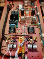
In pictures are original silent 15db version and reranged NFB version....Don't know what to do anymore....
BR,
Goran
Attachments
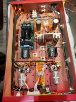
There is a cable harness at the left under side that touches a capacitor. Reroute that one. Of course the layout is not optimal. Sensitive/signal stuff is usually placed near the inputs for shortest wiring, least 50 Hz from PSUs etc. The way it is now AC wiring is often very near audio circuits and will be picked up. You have the extremely convenient luxury of a relay based volume control that could have been placed at the back near the RCA connectors. There is AFAIK a PSU with AC wiring close to the volume control. To make it worse there is even 230V AC mains wiring near the Janzen cap at the right side.
If the wiring is unshielded (it looks like that) well then you just know what to do as no one gets away with that 🙂 For silent devices one best arranges devices in sectors and the general rule is to keep inputs away from outputs, AC and PSUs as far away as possible from audio, to see mains voltage as your worst enemy for audio quality etc. If one analyzes this one can see many start arranging devices when building with their tubes as first parameter (eyecatcher). The tip is to arrange devices first technically and only then esthetically.
No sarcasm, just experience in building devices.
Last edited:
Too late to edit but if you drill a hole where now the screw of the screw connector near the IEC inlet is you can have a smaller mains voltage section by using a chassis mount fuse holder. The second mains voltage 3 pin screw connector too close to the RCA connectors should go too. A new hole near the existing hole would be OK. Or one could shield with a metal plate.
* Please use rubber grommets when pulling cabling through metal chassis.
The device probably already had hum but of less annoying level. In my humble opinion that build can not be silent.
* Please use rubber grommets when pulling cabling through metal chassis.
The device probably already had hum but of less annoying level. In my humble opinion that build can not be silent.
Last edited:
jean-paul,
I will do all that....thank you for take your time....
First I off all I'll put the shielding on signal and AC wires....
BR,
Goran
I will do all that....thank you for take your time....
First I off all I'll put the shielding on signal and AC wires....
BR,
Goran
No thanks. Sorry that I am right with the shielding. It is about the signal cables that should be shielded (certainly near AC environments) and the shield should be connected on only 1 side. Please always follow basic electric rules and don't focus on the tubes themselves too much as that won't improve your skills.
My tip is to draw the device 1:1 in sectors simply on A3 paper and you can even cut the sectors from another A3 paper and rearrange stuff with the AC connections drawn as red dots and the signal connections as green dots. Like a puzzle with the challenge to keep green as far away from red as possible. It works.
You'll notice that narrow and deep casings like yours are the most difficult to arrange internally with the now defined requirements of signal and AC/PSU/mains ... unless one uses them in width or whatever it is called in english.
Last edited:
I will try today....now I have NOS 6K6 Tungsol as before in 15db version....for almost two years....Will try 6V6....Did you try other tubes?
BR,
Goran
Your plate load resistors connected with wires maybe introduce enough inductance to set off an oscillation? NFB version would be more critical to such details. But first try regular 6V6 tubes.
- Home
- Amplifiers
- Tubes / Valves
- 6V6 line preamp