But your statement remain -> "Let's be clear, and I have said this many times, current-drive cannot lower driver distortion. The key to current-drive is that there is less amplifier distortion.!
//
... even if keeping SPL equal I suppose...The current and thus the acoustic distortion is reduced if you increase impedance in the circuit that is in series with voice coil at the 3kHz.
//
To keep SPL at some level the cone needs to make same excursion, current through voice coil needs to be same to make the cone move the same.
"Amount of backEMF voltage" can be thought to be always the same for any given excursion for the same driver, so for any given SPL. If we scale up impedance then current from backEMF goes down, distortion goes down. To keep the actual content we want to hear at the same SPL as before the voltage from our power amplifier needs to go up. Sometimes we dont want to keep it the same spl though, like with cone breakup.
What I have written is just a concept how to think about the topic, think about the driver having a voltage amplifier inside. Analyze its load impedance to evaluate how much current it makes. It is not necessary to know any of the details what goes into bbackEMF: increase impedance to reduce current from backEMF, decrease impedance to increase current from backEMF. Around drivers resonance the current can be utilized as electronic damping, and soon on frequen ies above its not useful and can be though to be only distortion. Now you know at which frequency one could benefit from increased or decreased impedance.
If the driver is good benefits aren't that great so its more useful to tune a crossover circuit for frequency response or cost or what ever, box alignment, mitigate effects of unknown amplifier output impedance, what ever feels most important.
tmikku, I am going to end the discussion right there. I simply cannot respond to everything that gets thrown into my face, often covering the same thing all over again.
You have not understood what I have said. It does affect distortion, but you have misinterpreted me and I am tired.
(Six posts by you in less than 24 hours, all aimed at...?)
Your words saying current-drive (in other words elevated circuit impedance) does not affect driver distortion, when it does.
You have not understood what I have said. It does affect distortion, but you have misinterpreted me and I am tired.
(Six posts by you in less than 24 hours, all aimed at...?)
Has anybody taken note that I am not even in the "current-drive" camp!!!
I have no compulsion to defend it.
I have no compulsion to defend it.
Hi,
I'm sorry, I understand it must feel an attack. I really have no bad feelings against you or your view, I'm trying to balance your powerful message which contains logic error for which I'm making a counter argument for. Trying to explain the counter argument and by answering subsequent questions the situation escalates. It is unfortunate the amplifier topology raises so much emotion, feel free to skip my posts if you wish and continue with other stuff. My posts are primarily ment for information seekers anyway.
I'm hiding the rest so its voluntary read.
Purpose of all my posts is to demonstrate how circuit impedance affects distortion of the driver turning into acoustic distortion. It is not promoting current-drive or any other amplifier or speaker tech, its promoting circuit analysis and logic that explains how this distortion mechanism with drivers and impedance works and how current drive actually reduces driver distortion. Not because a current-drive amplifier was somehow superior but because it makes high impedance in the circuit.
It is not a personal attack, it is counter argument for Joes message, for the quote I've been using:
Circuit analysis below shows how the loudspeaker driver makes its own distortion, and how a power amplifier is just an impedance for it. Current-drive amplifier with its high output impedance reduces driver distortion in acoustic domain. It does not have to be a current-drive amplifier though, any impedance in the circuit does the same thing, reduces current generated by backEMF.
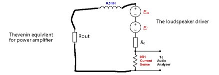
Here is the familiar circuit Joe has been using, our power amplifier on the left, loudspeaker on the right. The loudspeaker is split into its impedance, the backEMF voltage sources and resistance.
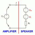
Same image redrawn to a format I can modify

The Em and Ei, the backEMF, can be thought as "distortion amplifiers", lets replace power amplifier with Thevenin equivalent to analyze what the current from them is, current means acoustic output.

Then magic trick arranges amplifiers to left, load to right like in the original image.

Suddenly we see there is "distortion amplifier" within the driver and has nothing to do with the actual power amplifier other than the power amplifier output impedance is in the circuit as load for it determining how much current backEMF "distortion amplifier" makes in the circuit, how much of it turns acoustic domain.
It is not a personal attack, it is counter argument for Joes message, for the quote I've been using:
Let's be clear, and I have said this many times, current-drive cannot lower driver distortion. The key to current-drive is that there is less amplifier distortion.
...
Circuit analysis below shows how the loudspeaker driver makes its own distortion, and how a power amplifier is just an impedance for it. Current-drive amplifier with its high output impedance reduces driver distortion in acoustic domain. It does not have to be a current-drive amplifier though, any impedance in the circuit does the same thing, reduces current generated by backEMF.
Here is the familiar circuit Joe has been using, our power amplifier on the left, loudspeaker on the right. The loudspeaker is split into its impedance, the backEMF voltage sources and resistance.

Same image redrawn to a format I can modify

The Em and Ei, the backEMF, can be thought as "distortion amplifiers", lets replace power amplifier with Thevenin equivalent to analyze what the current from them is, current means acoustic output.

Then magic trick arranges amplifiers to left, load to right like in the original image.

Suddenly we see there is "distortion amplifier" within the driver and has nothing to do with the actual power amplifier other than the power amplifier output impedance is in the circuit as load for it determining how much current backEMF "distortion amplifier" makes in the circuit, how much of it turns acoustic domain.
Last edited:
Joe, here is a suggestion; why don't you just use a market message / advertising scheme that 1) you offer an "impedance compensated loudspeaker that works well for all sorts of amplifiers", 2) don't talk so much about how things work inside your speakers - I don't think your typical audience know or care a lot about it anyway. Your way of constructing your own view of how reality is named and work don't fly in a more technical oriented environment - right or wrong - its a fact and this thread an others are proof of that. Wouldn't it be nicer to have a less annoying audio life? Its really up to you as I see it. Do honest "advertising" - don't mystify basic things in order to make it seem unique (in the hope for more sales?).
//
//
Hi tmuikku, thanks and much appreciated. I can assure you that I have no ignored your posts. It is a topic that is nevertheless interesting, but I have to say that I at least believe that something has flown below the radar and from my perspective puts voltage-drive back into the picture.
I have said the same thing, indeed I have been far more specific by saying that at any specific frequency the amplifier can only see a single impedance. And I have gone much futher than that. For example, an amplifier cannot see it own impedance (only if you short it, and that is not recommended) and indeed with pure current drive, the load impedance in theory is not even seen as an impedance. Indeed I have a tube amplifier and it measures 3 Ohm o/p @1KHz. The load is my Elsinores and they are 6 Ohm. So the amplifier @1KHz sees only a single impedance = 9 Ohm. It does not know the division point, where the tube o/p Z starts and when the Elsinore load starts, and not even the DC resistance of the of the voice coil. What does it say about damping factor then. Here is another area where I will get into trouble: The idea that the role of the amplifier is to provide damping one the current side is something I don't believe in. So now you can aim more shots at me I suppose.
So I am going to leave it there. Too bad you are not going to build the Elsinores and then current-drive them. Anybody who reads this can knock on my door and hear the Elsinore with current-drive. The bass is not lacking damping even with an amplifier with 270 Ohm output impedance:

This is a vented enclosure, the bump around 20 Hertz is not audible. If this was a sealed box, then there would be no bump at all.
In fact the bump only very slightly worsen the power handling, which is so enormous that it hardly matters.
So they are my calling card, they are the testament to what I am doing and I would pretty much invite others to compare with anything. The guys in New Zealand have already done that, so it is not an empty boast.
So there you go, a speaker that gets the best out of voltage drive AND current-drive.
BTW, there really is not such thing as voltage-drive. About 30% of the voice coil is inside the gap. The other 70% is not. The inductance is limited to the gap and so is the force-factor that makes the sound. That other 70% is largely acting as a split wire-wound resistor of 2 Ohm each x 2. But consider this, 100% of the current goes through the gap. Imagine having those resistors externally and that makes it visually obvious that there is no such thing as voltage-drive. Besides, in reality, it is the entire resistance of the VC and not just that part that is visually outside, makes the notion even more... well, you get the idea.
The term current-drive perhaps has a bit more validity, but I can pick on that one too. So we seem to be stuck with the terminology. Oh well.
As for your 'spoiler' it tells me nothing that I already know. I know all about Ei and Em (the Elsinores would not work without them, I wasn't born yesterday).
Can suppressing Ei reduce distortion? Absolutely!
I am at a loss why you would think that I would think otherwise. It is bewildering at times what I have to deal with here, and it is like a broken record.
Let me give you at challenge, look at the circuit below:

Call this inductor-drive. It has both the benefits of current-drive AND voltage-drive. At the most critical frequencies, up to 20dB reduction in distortion at critical frequencies, with the inductor forming a 3KHz low-pass filter.
Find the driver that can do this and you are in near heaven. Note that there is a 5:1 ratio
Now you analyse what is happening in that circuit and let me know. I am curious as to what you will come up with, what do you see?
You see, I ask questions, I don't assume the other person is an idiot. Know what I mean?
Circuit analysis below shows how the loudspeaker driver makes its own distortion, and how amplifier is just an impedance for it.
I have said the same thing, indeed I have been far more specific by saying that at any specific frequency the amplifier can only see a single impedance. And I have gone much futher than that. For example, an amplifier cannot see it own impedance (only if you short it, and that is not recommended) and indeed with pure current drive, the load impedance in theory is not even seen as an impedance. Indeed I have a tube amplifier and it measures 3 Ohm o/p @1KHz. The load is my Elsinores and they are 6 Ohm. So the amplifier @1KHz sees only a single impedance = 9 Ohm. It does not know the division point, where the tube o/p Z starts and when the Elsinore load starts, and not even the DC resistance of the of the voice coil. What does it say about damping factor then. Here is another area where I will get into trouble: The idea that the role of the amplifier is to provide damping one the current side is something I don't believe in. So now you can aim more shots at me I suppose.
So I am going to leave it there. Too bad you are not going to build the Elsinores and then current-drive them. Anybody who reads this can knock on my door and hear the Elsinore with current-drive. The bass is not lacking damping even with an amplifier with 270 Ohm output impedance:
This is a vented enclosure, the bump around 20 Hertz is not audible. If this was a sealed box, then there would be no bump at all.
In fact the bump only very slightly worsen the power handling, which is so enormous that it hardly matters.
So they are my calling card, they are the testament to what I am doing and I would pretty much invite others to compare with anything. The guys in New Zealand have already done that, so it is not an empty boast.
So there you go, a speaker that gets the best out of voltage drive AND current-drive.
BTW, there really is not such thing as voltage-drive. About 30% of the voice coil is inside the gap. The other 70% is not. The inductance is limited to the gap and so is the force-factor that makes the sound. That other 70% is largely acting as a split wire-wound resistor of 2 Ohm each x 2. But consider this, 100% of the current goes through the gap. Imagine having those resistors externally and that makes it visually obvious that there is no such thing as voltage-drive. Besides, in reality, it is the entire resistance of the VC and not just that part that is visually outside, makes the notion even more... well, you get the idea.
The term current-drive perhaps has a bit more validity, but I can pick on that one too. So we seem to be stuck with the terminology. Oh well.
As for your 'spoiler' it tells me nothing that I already know. I know all about Ei and Em (the Elsinores would not work without them, I wasn't born yesterday).
Can suppressing Ei reduce distortion? Absolutely!
I am at a loss why you would think that I would think otherwise. It is bewildering at times what I have to deal with here, and it is like a broken record.
Let me give you at challenge, look at the circuit below:
Call this inductor-drive. It has both the benefits of current-drive AND voltage-drive. At the most critical frequencies, up to 20dB reduction in distortion at critical frequencies, with the inductor forming a 3KHz low-pass filter.
Find the driver that can do this and you are in near heaven. Note that there is a 5:1 ratio
Now you analyse what is happening in that circuit and let me know. I am curious as to what you will come up with, what do you see?
You see, I ask questions, I don't assume the other person is an idiot. Know what I mean?
Joe, here is a suggestion
Ignored! What you are doing right there is trolling and you will get no response from me.
Hi,
thank you as well for responding.
yeah the current in the circuit is from voltage difference across the impedance, same current flows at any point, there is no more current on the amplifier and less on the driver, it all is the same current through out the circuit as long as its single circuit. If a shunt was introduced then there is multiple paths for current to flow and one could measure different current at different "legs" of the circuit.
I agree with you that the damping factor is misnomer and draws attention to itself when its all about circuit impedance. The amplifier does not do any damping, the driver does it by itself.
Current generated by the Em at drivers main resonance is the facilitator for electronic damping, it creates exactly opposite phase current into the circuit than the excitation and the current then dampens the movement, creates counter force in the voice coil that opposes the motion. As the power amplifier output impedance is part of the circuit it partly affects how much this damping current flows in the circuit, how much of the backEMF turns into damping force in the voice coil.
As you say we can do nothing about the impedance within the driver, but we can maintain the total circuit impedance at that of the driver or increase it further. Actually negative impedance amplifiers are something, but anyway. Impedance is frequency dependent, we can have "low" circuit impedance at low frequency to enable the damping current flow and then we can have "high" impedance higher up in frequency, to reduce distortion of the Ei for example. This is exactly what happens when you have inductor as 1st order low pass filter between amplifier and a driver. Impedance of the circuit stays "low" at low frequency but at high frequency the circuit impedance is "high". The high impedance makes the low pass filter by reducing current from your amplifier but it also reduces current from backEMF, which means less distortion acoustically.
Ok, for this one don't get emotional, but this is the exact motivation to post here:
I'm not sure if others see this conflict in these? Its the same underlying phenomenon under both of these phenomenon: increasing the circuit impedance in series with the driver reduces driver distortion. The first quote agrees with it, the second denies it. This conflict continues in your message post after post so I'm here to straighten it out.
Here is the circuit analysis like in the previous post.
Your circuit redrawn

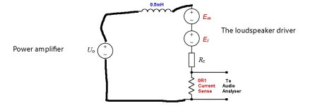
Thevenin equivalent so we can inspect circuit impedance to calculate what kind of current Ei would make.
Amplifiers to left, load on the right for familiar reading.
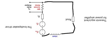
The inductor is load for Ei and increases circuit impedance or high frequencies. If you left the inductor out, you could increase the Rout instead for similarly high impedance for the Ei. Or add another resistor in there, or long thin cables. What ever suits the system.
See, here is your conflict: Rout would be high for a current-drive amplifier, which means high impedance for high frequency Ei and reduced distortion, just like the inductor with voltage amp does.
Difference between high Rout and the inductor for the system is of course the big Rout affects all frequencies, which reduces damping current for driver resonance from Em as well and you'd get no electrical damping and peaking bass response, unless current was reduced with EQ/mechanical damping increased. The inductor allows damping current to flow, while still reducing Ei distortion current.
thank you as well for responding.
So the amplifier @1KHz sees only a single impedance = 9 Ohm. It does not know the division point, where the tube o/p Z starts and when the Elsinore load starts, and not even the DC resistance of the of the voice coil. What does it say about damping factor then. Here is another area where I will get into trouble: The idea that the role of the amplifier is to provide damping one the current side is something I don't believe in. So now you can aim more shots at me I suppose.
yeah the current in the circuit is from voltage difference across the impedance, same current flows at any point, there is no more current on the amplifier and less on the driver, it all is the same current through out the circuit as long as its single circuit. If a shunt was introduced then there is multiple paths for current to flow and one could measure different current at different "legs" of the circuit.
I agree with you that the damping factor is misnomer and draws attention to itself when its all about circuit impedance. The amplifier does not do any damping, the driver does it by itself.
Current generated by the Em at drivers main resonance is the facilitator for electronic damping, it creates exactly opposite phase current into the circuit than the excitation and the current then dampens the movement, creates counter force in the voice coil that opposes the motion. As the power amplifier output impedance is part of the circuit it partly affects how much this damping current flows in the circuit, how much of the backEMF turns into damping force in the voice coil.
As you say we can do nothing about the impedance within the driver, but we can maintain the total circuit impedance at that of the driver or increase it further. Actually negative impedance amplifiers are something, but anyway. Impedance is frequency dependent, we can have "low" circuit impedance at low frequency to enable the damping current flow and then we can have "high" impedance higher up in frequency, to reduce distortion of the Ei for example. This is exactly what happens when you have inductor as 1st order low pass filter between amplifier and a driver. Impedance of the circuit stays "low" at low frequency but at high frequency the circuit impedance is "high". The high impedance makes the low pass filter by reducing current from your amplifier but it also reduces current from backEMF, which means less distortion acoustically.
I have no reason to believe the Elsinores sound wasn't very good. It seems to be good system and performs as you've demonstrated with the circuits, simulations and measurements. I'm not building them because they are not optimal for my application, for which I'm designing more suitable system. I utilize the circuit impedance for electrical damping and also for distortion reduction, voltage amplifier is perfect for this, I don't want current-drive amplifier, its less suitable for my system. I can understand a commercial speaker can benefit for the circuit you have to be able to cater all possible amplifiers people might have.So I am going to leave it there. Too bad you are not going to build the Elsinores and then current-drive them. Anybody who reads this can knock on my door and hear the Elsinore with current-drive. The bass is not lacking damping even with an amplifier with 270 Ohm output impedance:
Ok, for this one don't get emotional, but this is the exact motivation to post here:
Can suppressing Ei reduce distortion? Absolutely!
Let's be clear, and I have said this many times, current-drive cannot lower driver distortion. The key to current-drive is that there is less amplifier distortion.
I'm not sure if others see this conflict in these? Its the same underlying phenomenon under both of these phenomenon: increasing the circuit impedance in series with the driver reduces driver distortion. The first quote agrees with it, the second denies it. This conflict continues in your message post after post so I'm here to straighten it out.
I agree with you on this, this is exactly what would yield low distortion system. I understand you mean that we need a driver that works with 1st order filter and suits for a good loudspeaker system. What happens is circuit impedance is elevated for the high frequencies, which reduces backEMF current in the circuit. If you were to make it a second order filter by adding a shunt capacitor, the capacitor would provide very low impedance path for the high frequency backEMF current and the distortion would be back up. If you made it third order filter, there would be another coil and again high impedance for the high frequencies for the backEMF and distortion would be back down.Call this inductor-drive. It has both the benefits of current-drive AND voltage-drive. At the most critical frequencies, up to 20dB reduction in distortion at critical frequencies, with the inductor forming a 3KHz low-pass filter.
Find the driver that can do this and you are in near heaven. Note that there is a 5:1 ratio
Now you analyse what is happening in that circuit and let me know. I am curious as to what you will come up with, what do you see?
Here is the circuit analysis like in the previous post.
Your circuit redrawn


Thevenin equivalent so we can inspect circuit impedance to calculate what kind of current Ei would make.

Amplifiers to left, load on the right for familiar reading.

The inductor is load for Ei and increases circuit impedance or high frequencies. If you left the inductor out, you could increase the Rout instead for similarly high impedance for the Ei. Or add another resistor in there, or long thin cables. What ever suits the system.
See, here is your conflict: Rout would be high for a current-drive amplifier, which means high impedance for high frequency Ei and reduced distortion, just like the inductor with voltage amp does.
Difference between high Rout and the inductor for the system is of course the big Rout affects all frequencies, which reduces damping current for driver resonance from Em as well and you'd get no electrical damping and peaking bass response, unless current was reduced with EQ/mechanical damping increased. The inductor allows damping current to flow, while still reducing Ei distortion current.
Last edited:
Say for a full range single driver speaker, implementing the inductor strategy would imply a falling FR upwards which is not desirable. I suppose a electronic 1st order EQ compensation would bring it back to flat and the distortion reduction would remain - to the cost of more output power needed from the amplifier. This strategy should use an ordinary low output impedance amplifier or be moot. Correct?
//
//
^ Yes, exactly. In case of full range driver you could use high output impedance amplifier instead, which would do basically the same but possibly with less power loss. You might need to EQ it still so there would be some power loss if done passively.
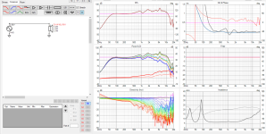
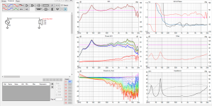
You would get EQ with high output impedance amplifier, or loss of EQ actually 🙂 Because with very high circuit impedance due to the high output impedance the driver impedance does not affect current in the circuit almost at all so you would get elevated highs and possibly some hump on the lows compared to frequency response you see on the driver datasheet.
With very low output impedance amplifier, the circuit impedance is almost all about the driver impedance, which means the impedance hump at drivers resonance and rising impedance due to voice coil inductance we see on datasheet limits current in the circuit, which reduces force in the voice coil, which reduces acoustic output. Basically the driver impedance is an EQ when it dominates circuit impedance. This is what we see on datasheet frequency response graphs because they are measured with constant voltage. If the datasheet frequency response were measured with constant current instead, with high circuit impedance, they wouldn't be as pretty.


Last edited:
Hi,
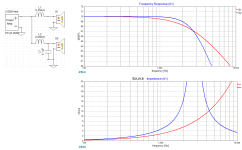
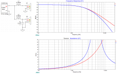
yeah around the xo the source impedance is higher you are right, source impedance skyrockets in comparison. But higher up in frequency the capacitor shunt has less and less impedance and basically provides short between driver terminals = high backEMF current. You see the source impedance drops back down around ~4kHz, so less distortion reduction above 4kHz in the example than with the 1st order filter.
Example, 2kHz would be pass band of the woofer in the example, 3rd order distortion for 2kHz tone from Ei would be at 6kHz. Which filter has higher source impedance at 6kHz and would measure less acoustic 3rd order harmonic distortion for 2kHz? Same question for 1kHz tone would yield opposite results.
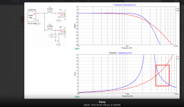
It is good excercise, anyone can utilize the circuit impedance as best suits in their application.
yeah around the xo the source impedance is higher you are right, source impedance skyrockets in comparison. But higher up in frequency the capacitor shunt has less and less impedance and basically provides short between driver terminals = high backEMF current. You see the source impedance drops back down around ~4kHz, so less distortion reduction above 4kHz in the example than with the 1st order filter.
Example, 2kHz would be pass band of the woofer in the example, 3rd order distortion for 2kHz tone from Ei would be at 6kHz. Which filter has higher source impedance at 6kHz and would measure less acoustic 3rd order harmonic distortion for 2kHz? Same question for 1kHz tone would yield opposite results.

It is good excercise, anyone can utilize the circuit impedance as best suits in their application.
Last edited:
Oh jeah, now its pretty high all the way past 10kHz, well utilized 😉
You could also add a parallel notch filter to tame a cone resonance. Compare to serial notch, both would same equalization for frequency response, but yield different source impedance and different distortion performance. This is the purifi paper.
What if it was active speaker with DSP filter, driver connected straight to "audiophile" amp with 0,00001ohm output impedance, using 1meter audiophile cables with cryogenic 0,000001ohm resistance/m?🙂 would it show higher or lower distortion from Ei than good old tube amp with 2ohm output impedance connected with thin lampcord with 1ohm resistance in the cable? Almost. What if the DSP 2nd order filter was replaced with 1st order filter and we had the series inductor in the circuit as well? It would have same frequency response with potentially less distortion.
It's about having a desirable low-pass and a suitable complimentary tweeter and getting additional benefits (3KHz crossover).
Maybe I should be glad, it seems that you guys haven't cottoned on how this works as a way to get lower distortion in a midrange driver.
It has all the advantages of both current-drive and voltage-drive.
But go ahead with your guesses.
Ask yourself, what mechanism is being suppressed?
Maybe I should be glad, it seems that you guys haven't cottoned on how this works as a way to get lower distortion in a midrange driver.
It has all the advantages of both current-drive and voltage-drive.
But go ahead with your guesses.
Ask yourself, what mechanism is being suppressed?
Its not guessing, its using knowledge/circuit analysis to deliberately reduce driver distortion with circuit impedance, adjusting load for the backEMF 😉
You are right the system needs to fit together in many ways. When drivers are good this stuff is not very important as the distortion is probably not audible so the additional benefits are less and less the better the drivers are and the bigger the systems is so drivers are not run at their excursion limits. Although, to get top performance any additional benefit is good, even small ones.
Logically, one would use DSP for the system so that the passive parts can be used solely for impedance and backEMF current manipulation. Now one can do what ever filters and hit any on-axis frequency response target and adjust circuit impedance separately, mucho more benefits. But a completely different system so its not straightforward comparison. Every system is different set of compromises.
Last edited:
An additional benefit of second order is a reduction in cone breakup distortions, such as polar response inconsistencies.It's about having a desirable low-pass and a suitable complimentary tweeter and getting additional benefits (3KHz crossover).
If I could show you the phase difference in this case it's less than 20 degrees at the cross if that's at 2800Hz. It's not the extra 45 degrees expected for another order, because this latest example uses a smooth response similar to the first order response in the pass band.
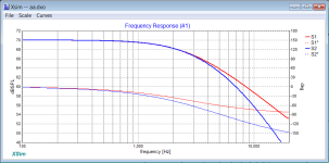
OK. 😉
No Allen, that's not it. I have mentioned online many times that parallel 8R resistor, but tmuikku may not have heard of it, so I will repeat it here and go to bed.
Tmuikikku, you seems to be hands-on and I like that. You may be able to try this depending what speakers you have and also that the results can vary from one speaker to another. But if you have an 8 Ohm speaker system, and let's face it, most are 2-Way ho-hum speaker designs that dominate much of the market. Particularly if the impedance looks like this with a large peak in the midrange area, typically 30 Ohm but often even higher, like almost 40 Ohm in this example:

Because it is 8 Ohm speaker, with most amplifiers you can safely add a 8 Ohm parallel resistor and get 4 Ohm nominal load. Easy-peasy. Needs to be rated at least 10 Watt. It will get warm.
Now listen to it.
Maybe you will hear something that will surprise you?
Nighty-night.
No Allen, that's not it. I have mentioned online many times that parallel 8R resistor, but tmuikku may not have heard of it, so I will repeat it here and go to bed.
Tmuikikku, you seems to be hands-on and I like that. You may be able to try this depending what speakers you have and also that the results can vary from one speaker to another. But if you have an 8 Ohm speaker system, and let's face it, most are 2-Way ho-hum speaker designs that dominate much of the market. Particularly if the impedance looks like this with a large peak in the midrange area, typically 30 Ohm but often even higher, like almost 40 Ohm in this example:
Because it is 8 Ohm speaker, with most amplifiers you can safely add a 8 Ohm parallel resistor and get 4 Ohm nominal load. Easy-peasy. Needs to be rated at least 10 Watt. It will get warm.
Now listen to it.
Maybe you will hear something that will surprise you?
Nighty-night.
Temperature dependent linearity problems? Slowly delayed varying compression probably...
//
//
- Home
- Loudspeakers
- Multi-Way
- The "Elsinore Project" Thread
