Hi ... I'm going to borosilicate beams. Tried to search the old linear thread, but didn't see what I was after.
I want to try two parallel tubes with a 4 ball bearing sled, two bearings on each side outboard at 45 deg and arm hanging between them.
I'm concerned with it wobbling as it moves along.
Zene
I want to try two parallel tubes with a 4 ball bearing sled, two bearings on each side outboard at 45 deg and arm hanging between them.
I'm concerned with it wobbling as it moves along.
Zene
Last edited by a moderator:
Off the subject a bit, but still in the potential problems category. No skating for linear arms of course, but the outer groove does have more stylis pressure on it. That to me is distortion.
Wouldn't a hanging weight on the end of beam help?
I know we are talking mini-gms here. The pulley /string should not effect the movement as is pulling not dragging.
Need some enlightenment.
Zene
Wouldn't a hanging weight on the end of beam help?
I know we are talking mini-gms here. The pulley /string should not effect the movement as is pulling not dragging.
Need some enlightenment.
Zene
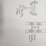
Here is a design suggestion for you.
The distance Y in the image is very important. It depends on the ball bearings you choose. I think it should be around 7-8 mm. The edge of the outer race of the ball bearing with the glass tubing may generate some damping factor. I don't think you need an extra pivot at all. The counterweight should be on the pivot line. The tip of the cartridge should be close to the pivot line as much as possible. I don't think 3 or 4 ball bearings make a huge difference. Personally, I prefer 4 ball bearings. Good luck with your build!

The distance Y in the image is very important. It depends on the ball bearings you choose. I think it should be around 7-8 mm. The edge of the outer race of the ball bearing with the glass tubing may generate some damping factor. I don't think you need an extra pivot at all. The counterweight should be on the pivot line. The tip of the cartridge should be close to the pivot line as much as possible. I don't think 3 or 4 ball bearings make a huge difference. Personally, I prefer 4 ball bearings. Good luck with your build!
Super ...
There is no way I can successfully build a stable platform on two rails, too many variables.
Main concern for this style you suggest (pivoting around the beam) was that a linear bearing is not designed to rotate. This will solve that problem and be very solid, indeed. Thx much for
your extra effort, Zene.
Yes. This causes VTF to vary. In the meantime, it generates a small damping force for warp records. Such character for a borosilicate glass tubing linear arm is almost inevitable. This is one of the reasons that I don't recommend this kind of linear arm. However, if you want to take that route, it may work for you.Main concern for this style you suggest (pivoting around the beam) was that a linear bearing is not designed to rotate.
Hi Zene,
I would never use the edge of a ball bearing to run on any kind of rail. I would only use the cylindrical portion of the ball bearing for that purpose.
The edges of the outer races of ball bearings are chamfered during the machining of the outer race blanks. It simply represents a deburring operation, to prevent sharp edges. Since the chamfer is machined before the final OD grinding of the outer race, the OD and the chamfer are not guaranteed to be concentric to each other. And last but not least, the surface finish of the chamfer is like sand paper compared to the cylindrical portion of the outer race.
If I were to design a ball bearing carriage, I would place two ball bearings on a cylindrical rail with the cylindrical portion of the bearings touching the rail and having an included angle of 90 Degrees between the bearings.
Also, placing the bearings on the rail as shown in your sketch, would tilt the leftmost bearing in a clockwise direction and it would tilt the rightmost bearing in a counter clockwise direction. The bearing balls would then not run properly seated in their grooves. To make a long story short, please don't do it. 🙂
Sincerely,
Ralf
Hi super10018,
In post #5, what you call the "Pivot Line", should run through the center of the glass rod.
The tone arm as shown, pivots on the center of the glass rod, not on the "Pivot Line".
The counterweight should not necessarily be located on the "Pivot Line", but should be located such as to cause the Center of Gravity of the whole tone arm to be located at the center of the glass rod.
Sincerely,
Ralf

Ralf .... Drat! This is harder than I thought to get right. Bearing orientation corrected, thx. Didn't consider machining even thought I built a test gyro for the first Lunar Lander and should know better. Wish I had some of the grade 9 bearings it used. Each has to be hand lapped to it's axle. We actually tested bearings by ear with bearing spinning on rod and holding it up to ear bone. Not as crude as it sounds.
90 degs to the tube makes building easier as the apex will be higher above the bearings.
Think I got the c.o.g., but just in case could you supply a simple sketch? You're talking to an engineering major college dropout.
Zene
90 degs to the tube makes building easier as the apex will be higher above the bearings.
Think I got the c.o.g., but just in case could you supply a simple sketch? You're talking to an engineering major college dropout.
Zene
Ralf,Hi super10018,
In post #5, what you call the "Pivot Line", should run through the center of the glass rod.
The tone arm as shown, pivots on the center of the glass rod, not on the "Pivot Line".
The counterweight should not necessarily be located on the "Pivot Line", but should be located such as to cause the Center of Gravity of the whole tone arm to be located at the center of the glass rod.
Sincerely,
Ralf
I can't agree with you. For my air-bearing arms, you are right. The pivot line is the center of the air-bearing shaft because the bearing has no contact with the shaft and it rotates around the circular shaft. The action forces and reaction forces are equally applied around the shaft through compressed air 360 degrees. Therefore, its pivot should be at the center of the shaft.
But for the linear arm here, there are 4 pivots. Although the 4 pivots may make very small movements vertically around the circular glass tubing, the edges of the ball bearings do contact with the glass tubing. These are the true pivots. These are the points where the action forces are applied to the glass tubing and the reaction forces from the glass tubing. The center of gravity of the arm should be the same level or slightly lower than these pivots, i.e. the pivot line.
Jim
Last edited:
Saturday April Fools thinking, so don't blame me:
I think it will take 5 bearings to do the job.
Four bearings sitting on top of the tube will have a rotational (looking down from top) movement plus a lot of drag as they cannot track perfectly.
Most bearings (I contacted Boca to get angle), are not 45 deg, which would be the most reasonable stable position on the tube. So, as the bearing moves up the side of the tube to approach bearing angle limits the problem gets worse.
One bearing on top to support arm and 2 on each side for stability should be a lot better. All would be 90deg to tube. Side pressure can be at a minimum.
There would be axles hanging from the tonearm for the side bearings and rubber bands below the tube to control the side pressure and eliminate noise.
Gotta lay off the Schnapps, Zene
Before the rain comes down on me. Yes, rotational friction will be bad.
Got reem of paper coming tomorrow.
Zene
Got reem of paper coming tomorrow.
Zene
1970 Schlumberger table (French 'table; specialty product, not for commercial sale)
I think this was only made for CEO's of major oil companies.
I think this was only made for CEO's of major oil companies.
Any movement around a circle the center of rotation or pivot point should be the center point of that circle regardless of its diameter.
DD,Any movement around a circle the center of rotation or pivot point should be the center point of that circle regardless of its diameter.
Ok. Tell me where is the pivot for the following cases. They work just like the one I proposed before.
Thx guys, from everything I've learned about standard ball bearings, it looks as if there is no great solution.
Going back to investigating radials and also researching teflon buttons on a teflon rod.
Wonder if that's been discussed?
PTFE has one of the lowest coefficients. Years ago the lowest was two soap bubbles sliding together...
Zene
Going back to investigating radials and also researching teflon buttons on a teflon rod.
Wonder if that's been discussed?
PTFE has one of the lowest coefficients. Years ago the lowest was two soap bubbles sliding together...
Zene
DD,Green dot is center of rotation.

Well, it seems to me that you tried to avoid my previous question. Anyway, I disagree with you and Ralf. I am not going to insist to change your view. 6 mm probably won't change the characteristics of the tonearm. I let the person who wants to adopt my proposal decides what he wants to do.

- Home
- Source & Line
- Analogue Source
- 0ld school linear arm