JMLC and TAD TH4001 (was Yuichi) horns
After enjoying Jean-Michel Le Cleac'h (JMLC) horns for several years, I've become curious about horns designed for broader horizontal directivity. Recently a pair of gently used pair of TAD TH4001 horns became available, which I decided to offer myself as a present. This thread shares measurements of two consecutive serial numbered Radian 745NEO drivers with beryllium diaphraghms installed on these two horn types.
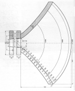
The JMLC 425 horn is 12 inches long, and its mouth measures 16.5 inches in diameter. This fiberglass horn was made by Azurahorn (fellow diyer Martin Seldon) and looks like this.

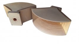
The TAD TH4001 horn is 16.25 inches long including a 1 inch thick throat adapter, and has a mouth measuring 24 by 9 inches. Key to its design are four fins contributing to horizontal dispersion of the acoustic wavefront. This wooden horn is from athosaudio.

In my view both horns are well designed and show solid craftsmanship.
Impedance was measured using REW, the sweep method, and a signal level of 200mV applied straight to the driver without protection capacitor.
First, the impedance plot on the JMLC 425 horn.

Second, the impedance plot on the TAD TH4001 (not Yuichi) horn.

The impedance plot for the JMLC shows one broad resonance and its curve is a little "ragged" only between 500 and 2,500 Hertz. The curve for the TAD shows two resonances of higher frequencies and is smoother. The curves differ significantly in the midrange. Similar anomalies are visible on both curves above 10 kHz.
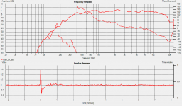
On-axis frequency response
All frequency responses were measured at a distance of 40 inches (1 m) to the exit of the driver. This is equivalent to 28 inches (0.71 m) to the mouth of the JMLC when on axis, and 24 inches (0,6 m) to the mouth of the TAD. The vertical scale reference is arbitrary, that is, the plots show relative, not absolute, decibels. I hesitated sharing measurements above 20 kHz considering my modest test set up. These are certainly not reliable, but given their similarity to the measurements made by Vance Dickason of the same driver on a ME90 horn, I decided to leave them in.
The plot below shows the on axis response of the driver fitted on the JMLC (in red) and TAD (in blue) horns without (top) and with (bottom) passive filtering and equalization. In the latter case, I used the same filter-EQ network on both horns. The specifics of this filter-EQ are irrelevant here, however the curves may be of interest for two-way speaker design.

The response on the JMLC is louder (as expected) by some 2.5 dB, more flat, and smoother between 1 and 4 kHz. It does not roll off as fast at higher frequencies than on the Yuichi. The response on the TAD exhibits more energy in the presence region. Note the dip around 725 Hz, close to a common crossover frequency. A small bump at 1.15 kHz corresponds to one of the two impedance peaks measured for this horn.
Tomorrow I will post horizontal off-axis frequency responses.
***
Edit 30 January 2023 - Post amended to reflect that the horns are TAD and not Yuichi as I originally believed.
Edit 4 February 2023 - See Post #49 for another measurement of impedance on the TAD horn using a longer throat adaptor.
After enjoying Jean-Michel Le Cleac'h (JMLC) horns for several years, I've become curious about horns designed for broader horizontal directivity. Recently a pair of gently used pair of TAD TH4001 horns became available, which I decided to offer myself as a present. This thread shares measurements of two consecutive serial numbered Radian 745NEO drivers with beryllium diaphraghms installed on these two horn types.
The JMLC 425 horn is 12 inches long, and its mouth measures 16.5 inches in diameter. This fiberglass horn was made by Azurahorn (fellow diyer Martin Seldon) and looks like this.
The TAD TH4001 horn is 16.25 inches long including a 1 inch thick throat adapter, and has a mouth measuring 24 by 9 inches. Key to its design are four fins contributing to horizontal dispersion of the acoustic wavefront. This wooden horn is from athosaudio.
In my view both horns are well designed and show solid craftsmanship.
Impedance was measured using REW, the sweep method, and a signal level of 200mV applied straight to the driver without protection capacitor.
First, the impedance plot on the JMLC 425 horn.
Second, the impedance plot on the TAD TH4001 (not Yuichi) horn.
The impedance plot for the JMLC shows one broad resonance and its curve is a little "ragged" only between 500 and 2,500 Hertz. The curve for the TAD shows two resonances of higher frequencies and is smoother. The curves differ significantly in the midrange. Similar anomalies are visible on both curves above 10 kHz.
On-axis frequency response
All frequency responses were measured at a distance of 40 inches (1 m) to the exit of the driver. This is equivalent to 28 inches (0.71 m) to the mouth of the JMLC when on axis, and 24 inches (0,6 m) to the mouth of the TAD. The vertical scale reference is arbitrary, that is, the plots show relative, not absolute, decibels. I hesitated sharing measurements above 20 kHz considering my modest test set up. These are certainly not reliable, but given their similarity to the measurements made by Vance Dickason of the same driver on a ME90 horn, I decided to leave them in.
The plot below shows the on axis response of the driver fitted on the JMLC (in red) and TAD (in blue) horns without (top) and with (bottom) passive filtering and equalization. In the latter case, I used the same filter-EQ network on both horns. The specifics of this filter-EQ are irrelevant here, however the curves may be of interest for two-way speaker design.
The response on the JMLC is louder (as expected) by some 2.5 dB, more flat, and smoother between 1 and 4 kHz. It does not roll off as fast at higher frequencies than on the Yuichi. The response on the TAD exhibits more energy in the presence region. Note the dip around 725 Hz, close to a common crossover frequency. A small bump at 1.15 kHz corresponds to one of the two impedance peaks measured for this horn.
Tomorrow I will post horizontal off-axis frequency responses.
***
Edit 30 January 2023 - Post amended to reflect that the horns are TAD and not Yuichi as I originally believed.
Edit 4 February 2023 - See Post #49 for another measurement of impedance on the TAD horn using a longer throat adaptor.
Last edited:

It would be nice if you could add a free-air impedance shot of the driver.
The design number A290 is not in line with the real loading capabilities of the horn which seems to be more in the higher frequency region above 400 Hz.
The design number A290 is not in line with the real loading capabilities of the horn which seems to be more in the higher frequency region above 400 Hz.
Last edited:
Only if I can be 100% sure that I will not damage the diaphragms... advice welcome.It would be nice if you could add a free-air impedance shot of the driver.
Vance Dickason has published a measurement already: see Figure 2, black curve Here.
It does seem so indeed.The design number A290 is not in line with the real loading capabilities of the horn which seems to be more in the higher frequency region above 400 Hz.
By all means! The loading of the two Iwatas appears to match well their 300 and 600 designations.Hey, I want to join!
The JA6681B driver is top by the way

Last edited:
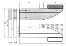
The fins are there to increase the acoustic loading of the horn without having to constrict the vertical to follow the expansion of the original hyp/ex it is based on.four fins contributing to horizontal dispersion of the acoustic wavefront.
It is best that the fins are presented with a good wavefront at the start, and they evenly distribute the ordinary expansion diffraction. If you count on the fins to enforce horizontal dispersion you can end up with higher order modes at their exit and along their length.
For this reason you are fortunate to require a throat adapter as this could be used as a substitute phase plug.
Last edited:
Could you show us a picture of your throat adapter please. iirc the Yuichi has a throat 50x50mm so a quite large throat area. When you start with an 1.4" driver round surface area and with fc=290 and T=1 you end up about 8.7 cm length for the throat adapter. But the Yuichi used a lower T value so the adapter must be even longer to provide correct loading.
Would you please elaborate on this and what is the root cause these HOMs, how we could prove their existence?It is best that the fins are presented with a good wavefront at the start, and they evenly distribute the ordinary expansion diffraction. If you count on the fins to enforce horizontal dispersion you can end up with higher order modes at their exit and along their length.
For this reason you are fortunate to require a throat adapter as this could be used as a substitute phase plug.
The five sub channels of course provide a better horizontal dispersion as you can see this as five different horns radiating in a conical bell. The Challenge is that the wave front should be coherent at the exit where the five channels combine. An appropriate throat adapter definitely help here. But the the five channels do not have the same length for a spherical wave front.
I'm using the Yuichi A-320FL model (also sometimes incorrectly referred to as A-290FL). It's very similar to the more famous A-290, but without the fins.
Its design parameters are Fc = 320Hz and T = 0.6.
I use it with a JBL 2450J 4" diaphragm/2" exit driver, equipped with a Truextent Beryllium diaphragm.
The internal geometry of this driver is an almost perfect match to this horn, in terms of maintaining the same flare rate at the transition between the driver's exit and the horn's throat - and that is an important factor in obtaining the best performance from any driver+horn combo.
Of course, this is no coincidence, since the Yuichi 2" horns were all designed for the TAD TD-4001 driver, which has an almost identical internal geometry to the JBL 2450...
Here is the on-axis frequency response, measured indoors at 1m, with no "protection" capacitor or any other high-pass filter, but with some slight high-frequency Eq. provided by a passive RC filter.
Good loading down to the cut-off frequency (-6dB @ 320Hz), and pretty flat and free from resonances up to 17kHz.
Marco
Attachments
Last edited:
@marco_gea
Loading of the FL version with this horizontal profile as shown is not possible. Do you also have the vertical profile?
Loading of the FL version with this horizontal profile as shown is not possible. Do you also have the vertical profile?
The Yuichi A-290 has a hypex expansion, with Fc = 290Hz and T = 0.7Could you show us a picture of your throat adapter please. iirc the Yuichi has a throat 50x50mm so a quite large throat area. When you start with an 1.4" driver round surface area and with fc=290 and T=1 you end up about 8.7 cm length for the throat adapter. But the Yuichi used a lower T value so the adapter must be even longer to provide correct loading.
Here is the vertical profile.@marco_gea
Loading of the FL version with this horizontal profile as shown is not possible. Do you also have the vertical profile?
"Not possible" is a funny observation, since it seems to contradict the empirical evidence...
Attachments
That's likely due to a mismatch with the internal geometry of the Radian 745NEO driver (which is probably characterized by a somewhat "rapid flare" throat).It would be nice if you could add a free-air impedance shot of the driver.
The design number A290 is not in line with the real loading capabilities of the horn which seems to be more in the higher frequency region above 400 Hz.
What I gave was a statement and not an observation and it was for sure not funny.Here is the vertical profile.
"Not possible" is a funny observation, since it seems to contradict the empirical evidence...
One cannot simply remove the fins of a horn and believe that it is working as the fin version. What I meant was exponential loading is not possible with this horn. You will end with something like this:
Some time ago @DonVK, @fuid and me we investigated intensively the Yuichi horn and extended the investigations with my own fin horn constructions. The shown impedance is from a horn that was designed with fins but having the fins removed. You will never have exponential loading in this case.
Just do a BEM simulation of your horn and you will see it what is funny.
That's likely due to a mismatch with the internal geometry of the Radian 745NEO driver (which is probably characterized by a somewhat "rapid flare" throat).
I doubt what you write. Although a driver like this Radian maybe is not optimal to use it together with the Yuichi simply look at the impedance of the 745Neo attached to a true exponential loading horn JMLC 425. The impedance is totally different to the drivers free-air impedance while attached to the Yuichi it is almost similar to the free-air impedance. This indicates that maybe the throat adapter is too short or has a mismatching flare rate. We will see when Pierre provides some more info about the throat adapter.
Statement or observation, it was incorrect.What I gave was a statement and not an observation and it was for sure not funny.
One cannot simply remove the fins of a horn and believe that it is working as the fin version. What I meant was exponential loading is not possible with this horn. You will end with something like this:
View attachment 1135916
Some time ago @DonVK, @fuid and me we investigated intensively the Yuichi horn and extended the investigations with my own fin horn constructions. The shown impedance is from a horn that was designed with fins but having the fins removed. You will never have exponential loading in this case.
Just do a BEM simulation of your horn and you will see it what is funny.
And the A320FL is not simply the A290 "with the fins removed". It is an entirely different horn, designed from the ground up by Mr. Arai to provide hypex (not exponential) loading without the fins. The horizontal and vertical profiles are different. And it works.
The throat adapters for all the Yuichi Arai horns are designed to the exact same Fc and T of the horns themselves, which are in turn designed to match the internal geometry of the TAD TD-4001 drivers.I doubt what you write. Although a driver like this Radian maybe is not optimal to use it together with the Yuichi simply look at the impedance of the 745Neo attached to a true exponential loading horn JMLC 425. The impedance is totally different to the drivers free-air impedance while attached to the Yuichi it is almost similar to the free-air impedance. This indicates that maybe the throat adapter is too short or has a mismatching flare rate. We will see when Pierre provides some more info about the throat adapter.
I have all the original MJ articles, as well as his book, where he explains all this (in Japanese).
Any other driver that is significantly different in terms of internal geometry will be a mismatch.
Please stay precise. I never said that the horn is not working. I stated that from the plans provided it cannot have true exponential loading over the entire length. Only the throat section has a low flare rate but suddenly the horizontal profile opens up suddenly with a very wide angle without that the vertical is accounting for it (it must contract for exponential loading). This is simple math. If we change the view onto the design where the vertical starts to expand you may have exponential loading from here with a virtual horn entry (where normally the fins end). But from throat to to this point the impedance will look like the picture I posted before.Statement or observation, it was incorrect.
And the A320FL is not simply the A290 "with the fins removed". It is an entirely different horn, designed from the ground up by Mr. Arai to provide hypex (not exponential) loading without the fins. The horizontal and vertical profiles are different. And it works.
Last edited:
Sorry, do you really read my posts or do you only repeat some historical info? It is for sure possible to design a throat adapter that is optimal for the Radian 745NEO. This is again simple math from a round 1.4" driver exit which has a distinct surface area and the 50x50mm Yuichi throat surface area. Using the desired T value you can exactly calculate the length of the adapter and also the coordinates at each increment of the adapter.The throat adapters for all the Yuichi Arai horns are designed to the exact same Fc and T of the horns themselves, which are in turn designed to match the internal geometry of the TAD TD-4001 drivers.
I have all the original MJ articles, as well as his book, where he explains all this (in Japanese).
Any other driver that is significantly different in terms of internal geometry will be a mismatch.
Could you show us a picture of your throat adapter please. iirc the Yuichi has a throat 50x50mm so a quite large throat area. When you start with an 1.4" driver round surface area and with fc=290 and T=1 you end up about 8.7 cm length for the throat adapter. But the Yuichi used a lower T value so the adapter must be even longer to provide correct loading.
Throat Adaptor
The throat of my Yuichi 290 measures 1 31/32 x 1 9/16 inch (50 x 40 mm). The throat adaptor that I used for testing has an entrance diameter of 1 3/8 inch (35 mm). So the surface expands from 1.5 to 3 inch^2 (a factor of two) over a length of just 7/8 inch (2.3 cm).
The horns came with another throat adaptor that has an entrance diameter of 2 inches and length of 3/4 inch. Alas there is no expansion of area at all along that length. So adding a round 1.4 to 2 inch adaptor in front of this one does not seem ideal, however this might load the driver better than using the "stubby" one. I would need to get that round-to-round adaptor to try this.
Since my horizontal measurements are already made using the "stubby" throat adaptor , let me share them with the caveat that the driver-to-horn adaptor was not optimized.
- Home
- Loudspeakers
- Multi-Way
- JMLC and Yuichi horns measurements