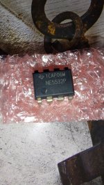
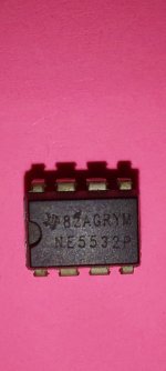
Hi, just bought some NE5532P from a good supplier but I wonder if they are fake or not.
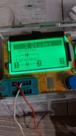
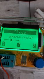
Tested pins 2-3 diode test, it says diode .
Saw a video on youtube that said clones dont have diodes on pin 2-3.
From google pictures the ne5523 has a dip in the top middle for proper positioning. The P version has a dot .
Anyway, here is a pic.
Tested pins 2-3 diode test, it says diode .
Saw a video on youtube that said clones dont have diodes on pin 2-3.
From google pictures the ne5523 has a dip in the top middle for proper positioning. The P version has a dot .
Anyway, here is a pic.
Attachments
This may be true with your meter - but not with most other DVM on this planet. The diode test is a better indicator.Test pin 1 and 8 to pin 7 resistance .should be 12...13kohms

Tested pins 2-3 diode test, it says diode .
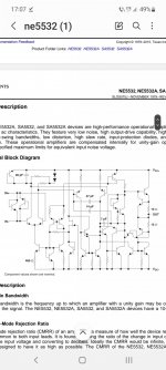
Do you see a normal silicon diode forward drop in both directions, and also between pins 5 and 6? If so, then at least the protection diodes for the input stages are there.
If it were fake, they would probably have printed NE5532AP on it rather than NE5532P, as the A version has better noise specs.
A diode test tells you NOTHING about Op Amp specs or quality.
Plug it into protoboard, set it up for 100X gain (100k/1k NFB resistors), feed it 100X attenuated signal on non inverting pin (again use 100k-/1k), output should basically be the same as input.
A 741 type Op Amp (the minimum spec out there) will drop about 6dB @10kHz, TL07X around 30 kHz.
If too high for your test equipment (say you use a standard Soundcard, just double gain/NFB resistor ratio (say 220k/1k or even 330k/1k) so bandwidth drops even more.
You can also apply a 10kHz squarewave to the same setup, and look what you get at the output.
"The proof of the pudding lies in the eating", this is a functional test, no way to cheat it if device does not actually deliver.
You can also measure noise: short +IN to ground, (always with the "revealing" 100X attenuation/gain setup), feed output to another 100X gain block, noise will be amplified 10000 times and easily visible on any scope, even a Software one.
Once you have real bandwidth and noise, you can easily tell "good" from junk.
No. The inputs of original NE5532 has two antiparallel clamp diodes - input differential voltage thus is restricted to +- 0,3V. Not so LM358 that allowes a big differentiel input voltage. And this in fact can easily be discerned by any diode testing. Go figure!A diode test tells you NOTHING about Op Amp specs or quality.
Plug it into protoboard, set it up for 100X gain (100k/1k NFB resistors), feed it 100X attenuated signal on non inverting pin (again use 100k-/1k), output should basically be the same as input.
A 741 type Op Amp (the minimum spec out there) will drop about 6dB @10kHz, TL07X around 30 kHz.
If too high for your test equipment (say you use a standard Soundcard, just double gain/NFB resistor ratio (say 220k/1k or even 330k/1k) so bandwidth drops even more.
You can also apply a 10kHz squarewave to the same setup, and look what you get at the output.
"The proof of the pudding lies in the eating", this is a functional test, no way to cheat it if device does not actually deliver.
You can also measure noise: short +IN to ground, (always with the "revealing" 100X attenuation/gain setup), feed output to another 100X gain block, noise will be amplified 10000 times and easily visible on any scope, even a Software one.
Once you have real bandwidth and noise, you can easily tell "good" from junk.
Measuring the supplies pins with an ohm-meter is a totally different story - the numbers will greatly vary depending on the ohmmeter you use.
There is many version of it, currently i hve three typ of 5532. I bought NE5532AP from rs components & others from local suppliers.


The more relevant question is: are there any op-amps cheaper than an NE5532P having anti-parallel diodes across their inputs?Just curious, any other Op Amp uses antiparallel cross-input diodes?
All decent low-noise op-amps with an NPN input stage have such diodes to prevent base-emitter avalanching (which could damage the transistors and increase their 1/f noise), but all the ones I'm aware of are more expensive than an NE5532 (except the NE5532 itself, which costs exactly as much as an NE5532).
Pins 2-3 and 5-6Do you see a normal silicon diode forward drop in both directions, and also between pins 5 and 6? If so, then at least the protection diodes for the input stages are there.
If it were fake, they would probably have printed NE5532AP on it rather than NE5532P, as the A version has better noise specs.
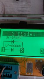
Tested with multimeter and also cheap LCR Meter .
Attachments
Sadly I don't own an oscilloscope .A diode test tells you NOTHING about Op Amp specs or quality.
Plug it into protoboard, set it up for 100X gain (100k/1k NFB resistors), feed it 100X attenuated signal on non inverting pin (again use 100k-/1k), output should basically be the same as input.
A 741 type Op Amp (the minimum spec out there) will drop about 6dB @10kHz, TL07X around 30 kHz.
If too high for your test equipment (say you use a standard Soundcard, just double gain/NFB resistor ratio (say 220k/1k or even 330k/1k) so bandwidth drops even more.
You can also apply a 10kHz squarewave to the same setup, and look what you get at the output.
"The proof of the pudding lies in the eating", this is a functional test, no way to cheat it if device does not actually deliver.
You can also measure noise: short +IN to ground, (always with the "revealing" 100X attenuation/gain setup), feed output to another 100X gain block, noise will be amplified 10000 times and easily visible on any scope, even a Software one.
Once you have real bandwidth and noise, you can easily tell "good" from junk.
Vcc to output I get weird measurements with a multimeter. 1k ohm on 2k scale, 10k on 20k scale, 70k on 100k scale. Weird, normal resistors wouldnt measure at all if in wrong scale, or weird like that.anyway.Test pin 1 and 8 to pin 7 resistance .should be 12...13kohms
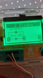
On LCR i get this.
Shows one diode from Vcc to output. Both channels the same.
from output 1 to output 2 . Shows two diodes. Based on internal diagram of ne5532 , shouldnt it be two diodes between output and vcc?
Attachments
Last edited:
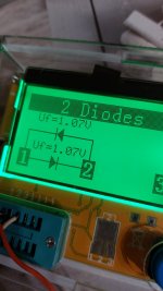
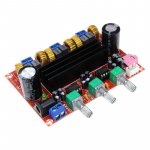
Also tested this NE5532 from this cheap tpa3116d2 board, which I tought are more likely fake. But Vcc to Output shows two diodes. Somewhat like the internal diagram.
Attachments


You should ask that question to fakers. These opamp costs next to nothing. You can buy 10-12 unit for $1USD. I hve exactly same type somewhere. But 5532p from post one looks good to me although not sure.
I've missed something here, the NE5532P isn't exactly expensive, so why would anyone even bother to fake it when there are much more expensive part numbers they could fake? TI components are widely available in China and that opamp is pretty cheap. (Not saying it isn't fake, but it's not the most logical part to counterfeit given likely return)
- Home
- Amplifiers
- Chip Amps
- Fake op amp or not