I've seen so many protection circuit failing miserably...comming from a "fix-repairs " background gives you a more realistic approach on designs issues 😉I didn't quite understand the question...
what does the cost of the speaker system matter if there is protection for 10 bucks.
this has not happened in the last 30 years. If this happens, I'll let you know.I've seen so many protection circuit failing miserably...comming
I do not repair, only scheme design only and modifyfrom a "fix-repairs " background
Thanks, I'm always on the lookout...you a more realistic approach on designs issues
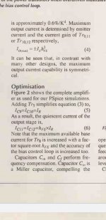
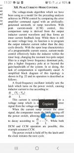
It was Dec 1999, page 982:I remember a design from Wireless World (can't remember the year but I have a paper copy somewhere) by Wim De Jager.
https://worldradiohistory.com/UK/Wireless-World/90s/Electronics-World-1999-12-S-OCR.pdf
Hi Tsz,Very interesting design Ian! Thanks for sharing!
How come there’s no risk of thermal runaway when the output transistors are current driven? The data sheet for MJL3281 shows an increasing hFE with temperature. Isn’t this a problem?
edit: I guess the increase of hFE with temperature is too low for runaway?
Thanks, a good question. A working 100W amplifier similar to the above has been tested and is thermally stable. It appeared in Linear Audio Vol 13 https://linearaudio.net/volumes/2282 and diyAudio (use link in Post 1 covering improvements).
The datasheet Beta/Hfe temp.co is about +0.4%/C. For voltage driven power transistors the temp.co. is -2.2mV/C or -0.3%/C at 25C and -0.4%/C at 70C. So at first sight current drive appears to be about as bad as voltage drive in terms of thermal runaway. So how is current driven power transistors more thermally stable? Bob Cordell's thermal loop analysis for current drive suggests it is typically about 6 times less sensitive to Tj than voltage drive. Analysis follows:
With voltage source drive the short term thermal feedback loop gain is
    βTh = TcVbe × dIc/dVbe × Vrail × Rjs
e.g. a typical 150W amplifier with 54V rails and two pairs of TO-264 output transistors, TO-264 case with a thermal washer is typically θjs of 1.1°C/W. Each transistor has RE = 0.22 Ω and is optimally biased at 118 mA and the net transconductance including RE is ~1/(2×RE)=2.3 A/V. So  βTh = 2.2 mV/°C × 2.3 S × 54 V × 1.1°C/W = 0.30 (β here a dimensionless feedback factor the '1+βA' in text books). Since βTh this is less than 1 the short term thermal stability is adequate with 0.22 ohm emitter resistors with 54V rails.
With current source drive the short term thermal feedback loop gain is
    βTh = TcHfe × Iq × Vrail × Rjs
For the same 150W amplifier with 54V rails and two pairs of TO-264 output transistors. Each transistor is optimally biased at 205 mA. and the TO-264 case with a thermal washer is typically θjs of 1.1°C/W. So βTh = 0.44 %/°C × 0.2.5 A × 54 V × 1.1°C/W = 0.06
So the thermal stability is adequate. It is about 6 times less sensitive than the standard voltage driven output stage.
The current increase in the power transistors with temperature under current drive scales the gain of the drivers and does not change the wingspread curve shape and hence the harmonic structure is not changed by temperature changes in the power transistors. IIRC the idle current increased about 30% from cold to hot.
With typical feedback this gain change is below 1dB and becomes unnoticeable. Under standard voltage drive output stage wingspread plots change with temperature changes in the power transistors, particularly in the short term, maybe for 5-10 minutes, until the bias loop stabilizes. Although with enough feedback such changes in distortion can be made inaudible, that is not always achieved in practice such as to poor thermal loop design, or manufacturing hiccups or servicing issues.
Also paralleling of several power transistors with current drive can be made thermally stable by using a 330 ohm base resistors (base stopper resistors). The Bth feedback factor between transistors is then about 0.02 indicating no current hogging.
Hi Damir,Hi Ian,
Do I see it correctly, local NFB network uses very low value resistors and it will consume a half ouput power?
You used dadod for FFT liles??
I like your approach and new ideas, as always very interesting.
BR Damir
The local feedback is the load!. It is just drawn in an unusual way. The usual way is a current sense resistor in series with the load in a vertical fashion.
It gives current feedback. Also called a transconductance amp. Although my circuit looks like a CFA it is not a CFA. When you add an opamp you can get voltage feedback for driving loudspeakers. But if you want a transconductance amp with an opamp then take the feedback to the opamp from the 0.22 ohm resistor.
My apology for using your name in the headers of the FFT pictures in Post 2😳. That arose from simulating your circuit here https://www.diyaudio.com/community/threads/common-base-input-for-power-amplifier.387450/post-7097415
It then evolved into this thread. Then I changed the name to CSD for this thread. But had already done the screen captures with the legacy file names, and didn't go back and do them again to update the headers. Maybe no one else noticed 😉 .
Nice that you like new ideas. Thanks for your like👍. It makes a world of difference to me.
Thanks Mooly,It was Dec 1999, page 982:
https://worldradiohistory.com/UK/Wireless-World/90s/Electronics-World-1999-12-S-OCR.pdf
I had forgotten that. Yes, it does use current drive to the power transistors. Notice there are no base-emitter resistors.
They use very fast power transistors to keep the cross-conduction low enough at 20kHz (from slow turnoff with no base-emitter resistors).
The ingenious part of their design is the bias loop (aka autobias).
There have been several threads discussing it an improving it. IIRC keantoken (member) found a way to reduce distortion by about a factor of 10, similar to standard topology figures, but I can't find it now.
Hi Ian,Hi Damir,
The local feedback is the load!. It is just drawn in an unusual way. The usual way is a current sense resistor in series with the load in a vertical fashion.
It gives current feedback. Also called a transconductance amp. Although my circuit looks like a CFA it is not a CFA. When you add an opamp you can get voltage feedback for driving loudspeakers. But if you want a transconductance amp with an opamp then take the feedback to the opamp from the 0.22 ohm resistor.
My apology for using your name in the headers of the FFT pictures in Post 2😳. That arose from simulating your circuit here https://www.diyaudio.com/community/threads/common-base-input-for-power-amplifier.387450/post-7097415
It then evolved into this thread. Then I changed the name to CSD for this thread. But had already done the screen captures with the legacy file names, and didn't go back and do them again to update the headers. Maybe no one else noticed 😉 .
Nice that you like new ideas. Thanks for your like👍. It makes a world of difference to me.
My first thought was, the local feedback is via the load, but then if the loudspeaker is part of the NFB and loudspeakers are not constant resistance and inductance, how it is going to influence the NFB?
I suppose this is just an idea not suppose to be in real amp?
BR Damir
They use very expensive matched SSM trz and unotainium 150 watts 60 Mhz transistors to achieve 7v/us slew rate...I can understand the urge for novelty, but with such high speed trz they still need Cm and Cf for compensation to keep the max current gain symmetrical at 20khz...at least with a Szikay they'd have naturally equal gm from multiplying npn x pnp gains .Thanks Mooly,
They use very fast power transistors to keep the cross-conduction low enough at 20kHz (from slow turnoff with no base-emitter resistors).
It's cool to see the theoretical effort to keep everything under control, three design guys(the students)
plus another 5 guys(the professors) plus D Self , Tanaka , Gray and Grabene(obviously the last 2 guys provided the theoretical support for the choice of matched SSM trz...) being mentioned as background theoretical support , other than that I see no real beneffits in wasting so many resources to get in the end to the use of Cf Cm , 60 Mhz/150 Watt trz and achieving 7v/us....That's the realm of TDA2040.
Attachments
Last edited:
Hi Damir,Hi Ian,
My first thought was, the local feedback is via the load, but then if the loudspeaker is part of the NFB and loudspeakers are not constant resistance and inductance, how it is going to influence the NFB?
I suppose this is just an idea not suppose to be in real amp?
BR Damir
With a transconductance amp the current through the speaker is forced to follow the amps input voltage. This gives a lower distortion in ordinary speaker drivers, but transconductance mode is not compatible with standard passive crossovers (they are designed only for a voltage source/drive).
If you are unfamiliar with transconductance amp speaker drive (aka current driven speakers)? See Esa Merilainen website https://www.current-drive.info/
His peer reviewed paper 'Comparative Measurements on Loudspeaker Distortion: Current vs. Voltage Control' under well controlled conditions and at moderate SPL? It's here and PDF download here http://acousticsnew.ippt.gov.pl/index.php/aa/article/download/1780/pdf_255
It was a surprise to me that there was such a large difference in distortion readings with current drive at normal listening power levels of around 1W compared to standard voltage speaker drive.
The reason it is not used commercially (apart from active speakers) is it is not compatible with standard loudspeakers and no one wants to throw them away just to change over to current drive. But DIY can easily do the required changes. Also Guitar amps sometimes use it, with a pot to vary the percentage mix between voltage and current drive, eg, here http://copyright.lenardaudio.com/laidesign/images/a12/a12_cd-management.gif.
So I am seriously suggesting using current drive of your loudspeakers using my circuit as suggest in my Post 26.
Hi Damir,
With a transconductance amp the current through the speaker is forced to follow the amps input voltage. This gives a lower distortion in ordinary speaker drivers, but transconductance mode is not compatible with standard passive crossovers (they are designed only for a voltage source/drive).
If you are unfamiliar with transconductance amp speaker drive (aka current driven speakers)? See Esa Merilainen website https://www.current-drive.info/
View attachment 1083823
His peer reviewed paper 'Comparative Measurements on Loudspeaker Distortion: Current vs. Voltage Control' under well controlled conditions and at moderate SPL? It's here and PDF download here http://acousticsnew.ippt.gov.pl/index.php/aa/article/download/1780/pdf_255
It was a surprise to me that there was such a large difference in distortion readings with current drive at normal listening power levels of around 1W compared to standard voltage speaker drive.
The reason it is not used commercially (apart from active speakers) is it is not compatible with standard loudspeakers and no one wants to throw them away just to change over to current drive. But DIY can easily do the required changes. Also Guitar amps sometimes use it, with a pot to vary the percentage mix between voltage and current drive, eg, here http://copyright.lenardaudio.com/laidesign/images/a12/a12_cd-management.gif.
So I am seriously suggesting using current drive of your loudspeakers using my circuit as suggest in my Post 26.
Hi Ian,
Ok my bad. I have that Electronics World (and many others) and keep it on separate place where I have it to read it carefully again. It was long time ago with no spice available and not easy to test all kind of feedback.
Now I will reread it again, thanks Ian.
I have Orion speakers with active analogue crossovers(Linkwitz) before output power amps.
Do you think about using transconductance amps instead voltage drive amps (CFA) I am using now, do I need to change something in the existing crossovers?
BR Damir
Attachments
For some reason I can't acces that pdf.Yet this concept isn't anything but new.Including the speaker inside the feedback loop does ideed give wonderful results at low power , but is prone to variable damping factor at high power and final silicon transistor transconductance isn't the same thing with tubes transconductance even when you disregard output transformer saturation.The amplifier response at high power depends heavily on the feedback speed and feedback response law .Making it square response to sym a tube amp with silicon trz is just another problem and on top of that the global feedback loop ability to slow down the amp is not the same thing with a power device automatic response when dealing with a sudden variation in impedance. A tube-transformer into a colapsing speaker impedance when driven out of the magnetic gap will never behave the same with a silicon based current amp driving the same load near clipping or in clipping.Apparently a voltage drive will use a voltage feedback better than a current drive in that area but you don't play joyful with voltage feedback when the clipping red led is on...Hi Damir,
With a transconductance amp the current through the speaker is forced to follow the amps input voltage. This gives a lower distortion in ordinary speaker drivers, but transconductance mode is not compatible with standard passive crossovers (they are designed only for a voltage source/drive).
If you are unfamiliar with transconductance amp speaker drive (aka current driven speakers)? See Esa Merilainen website https://www.current-drive.info/
View attachment 1083823
His peer reviewed paper 'Comparative Measurements on Loudspeaker Distortion: Current vs. Voltage Control' under well controlled conditions and at moderate SPL? It's here and PDF download here http://acousticsnew.ippt.gov.pl/index.php/aa/article/download/1780/pdf_255
It was a surprise to me that there was such a large difference in distortion readings with current drive at normal listening power levels of around 1W compared to standard voltage speaker drive.
The reason it is not used commercially (apart from active speakers) is it is not compatible with standard loudspeakers and no one wants to throw them away just to change over to current drive. But DIY can easily do the required changes. Also Guitar amps sometimes use it, with a pot to vary the percentage mix between voltage and current drive, eg, here http://copyright.lenardaudio.com/laidesign/images/a12/a12_cd-management.gif.
So I am seriously suggesting using current drive of your loudspeakers using my circuit as suggest in my Post 26.
This system might be better in active speakers just because of the active filters , but driving them near clipping will deffinitely need current feedback too not just current drive.You basically get the same problems as smps face with current feedback where they need both voltage feedback and current feedback and compare their results constantly.It's not just the difficulty of driving a crossover filter in parallel with a speaker, but also driving an inductor when it's out of the magnetic gap.Thus we arrive at class D amps which are pure current drive amps that are using all the knowledge accumulated by decades of smps design...
Attachments
@ dreanth Try this link https://acoustics.ippt.pan.pl/index.php/aa/article/view/1780/pdf_255 Then click download.
If that horizontal 8 ohms resistor between inv and Out marked RL is really the load, this design shows current feedback (NFB signal proportional to the output current), rersulting in a very high output impedance. Is this intended?
Best regards!
Best regards!
Perhaps this is it:...IIRC keantoken (member) found a way to reduce distortion by about a factor of 10, similar to standard topology figures, but I can't find it now.
https://www.diyaudio.com/community/...oss-conduction-distortion.305943/post-5043851
Thanks!@ dreanth Try this link https://acoustics.ippt.pan.pl/index.php/aa/article/view/1780/pdf_255 Then click download.
https://www.diyaudio.com/community/...er-amplifier-book.171159/page-28#post-2328159
https://www.diyaudio.com/community/...er-amplifier-book.171159/page-28#post-2329551
Unfortunately the information from Fidelix site dissapeared...but back emf can be fought successfuly with just 2 wires, two capacitors and 2 resistors or only one op amp reading the ground currents inside the amp... Of you never had such an amp don't worry.I had one and I never heard anything more neutral and a better controlled base.It kills any back emf, but you might not necessarily like it!
http://www.thevintageknob.org/kenwood-L-08M.html
https://ro.scribd.com/document/411868140/Kenwood-Sigma-Drive-Technical-Guide
Attachments
Based on post 29, i think he does intend current drive. Transconductance is consistent across speaker load with .22R current sense. Transconductance is (Gain at inverting node)/RSense, i.e. V(Inv)/V(in)/Rsense, at least for 8 ohm load and RS between .11 and 1R. Thats as far as I got so far, all in AC. Not sure how easy or worthwhile it is to increase Gain at inverting node, or how much it changes with signal.If that horizontal 8 ohms resistor between inv and Out marked RL is really the load, this design shows current feedback (NFB signal proportional to the output current), rersulting in a very high output impedance. Is this intended?
Best regards!
Attachments
The resistance of the triode output does not have much influence.
You're making this too complicated.
I think you should put complex problems. I think it's simpler.
The power amplifier is like a regulated power supply. Refer to my link.
The resistance of the output of a regulated power supply. But it is within the feedback circuit.
Does it change the output voltage. Theoretically, it will not.
https://www.diyaudio.com/community/...ss-d-is-class-ab-class-a.388305/#post-7076023
Hi Tsz,
Thanks, a good question. A working 100W amplifier similar to the above has been tested and is thermally stable. It appeared in Linear Audio Vol 13 https://linearaudio.net/volumes/2282 and diyAudio (use link in Post 1 covering improvements).
The datasheet Beta/Hfe temp.co is about +0.4%/C. For voltage driven power transistors the temp.co. is -2.2mV/C or -0.3%/C at 25C and -0.4%/C at 70C. So at first sight current drive appears to be about as bad as voltage drive in terms of thermal runaway. So how is current driven power transistors more thermally stable? Bob Cordell's thermal loop analysis for current drive suggests it is typically about 6 times less sensitive to Tj than voltage drive. Analysis follows:
With voltage source drive the short term thermal feedback loop gain is
    βTh = TcVbe × dIc/dVbe × Vrail × Rjs
e.g. a typical 150W amplifier with 54V rails and two pairs of TO-264 output transistors, TO-264 case with a thermal washer is typically θjs of 1.1°C/W. Each transistor has RE = 0.22 Ω and is optimally biased at 118 mA and the net transconductance including RE is ~1/(2×RE)=2.3 A/V. So  βTh = 2.2 mV/°C × 2.3 S × 54 V × 1.1°C/W = 0.30 (β here a dimensionless feedback factor the '1+βA' in text books). Since βTh this is less than 1 the short term thermal stability is adequate with 0.22 ohm emitter resistors with 54V rails.
With current source drive the short term thermal feedback loop gain is
    βTh = TcHfe × Iq × Vrail × Rjs
For the same 150W amplifier with 54V rails and two pairs of TO-264 output transistors. Each transistor is optimally biased at 205 mA. and the TO-264 case with a thermal washer is typically θjs of 1.1°C/W. So βTh = 0.44 %/°C × 0.2.5 A × 54 V × 1.1°C/W = 0.06
So the thermal stability is adequate. It is about 6 times less sensitive than the standard voltage driven output stage.
The current increase in the power transistors with temperature under current drive scales the gain of the drivers and does not change the wingspread curve shape and hence the harmonic structure is not changed by temperature changes in the power transistors. IIRC the idle current increased about 30% from cold to hot.
With typical feedback this gain change is below 1dB and becomes unnoticeable. Under standard voltage drive output stage wingspread plots change with temperature changes in the power transistors, particularly in the short term, maybe for 5-10 minutes, until the bias loop stabilizes. Although with enough feedback such changes in distortion can be made inaudible, that is not always achieved in practice such as to poor thermal loop design, or manufacturing hiccups or servicing issues.
Also paralleling of several power transistors with current drive can be made thermally stable by using a 330 ohm base resistors (base stopper resistors). The Bth feedback factor between transistors is then about 0.02 indicating no current hogging.
Thanks for your comprehensive reply Ian! A lot of useful information!
Makes sense that it's the fast thermal loop (with θjs) that determines whether we get thermal runaway. And I suppose the slow loop (with θja) determines idle current change from cold to hot.
Tobias
#7, #12 http://archive.radio.ru/web/1991/03/056/
Dorofeev's amplifier, which is very popular with Russian DIY.
Dorofeev's amplifier, which is very popular with Russian DIY.
Hi tcz,Thanks for your comprehensive reply Ian! A lot of useful information!
Makes sense that it's the fast thermal loop (with θjs) that determines whether we get thermal runaway. And I suppose the slow loop (with θja) determines idle current change from cold to hot.
Tobias
Yes, the fast thermal feedback loop is with the emitter resistor and thermal drop junction up to the heatsink which has the thermal sensor on it. The slow thermal loop is the thermal sensor loop which has several poles.
BTW if you run the simulation I provided you should find the power transistor temp co under current drive has next to no temp co. I suspect the temp co. for the model Beta/Hfe has not been correctly set (or not at all). Has anyone else noticed this? I'm using the Cordell model.
My bench version for the Linear Audio article did show a rise in current after warm up but it was not as much change as suggested by the datasheet plots.
- Home
- Amplifiers
- Solid State
- Class-AB with no emitter resistors and good thermal stability and good sound

![20220823_092924[1].jpg](/community/data/attachments/991/991744-7afb6ebd40f05cadf3dcd2f002c8eecc.jpg?hash=evtuvUDwXK)


