Hi,
Recently acquired a Leak Stereo 30 plus with only one channel working and I find that 3 transistors are defective on the power amp board.
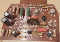
A resistor also looks suspect (burn stains around it) so I will be checking these too. Looking at the resistors I see that 5 look different from the other conventional axial lead soldered into the boards, these seem to have vertical metal tabs. Could they be wire wound? I would appreciate some advice on this please in case I need to renew some.
Also, does anyone know the type of resistors used on this board in addition to the ones already mentioned? The circuit diagram gives their value but not the wattage.
I’ve included some photos of the board which I hope will help.
Thanks,


Recently acquired a Leak Stereo 30 plus with only one channel working and I find that 3 transistors are defective on the power amp board.
A resistor also looks suspect (burn stains around it) so I will be checking these too. Looking at the resistors I see that 5 look different from the other conventional axial lead soldered into the boards, these seem to have vertical metal tabs. Could they be wire wound? I would appreciate some advice on this please in case I need to renew some.
Also, does anyone know the type of resistors used on this board in addition to the ones already mentioned? The circuit diagram gives their value but not the wattage.
I’ve included some photos of the board which I hope will help.
Thanks,

Those and the ones with painted on codes may indeed be wirewounds.
I would use the highest power rating for the new resistors that will fit the pcb properly.
I would use the highest power rating for the new resistors that will fit the pcb properly.
The green ones are the output stage emitter resistors, probably 1W. No need for them to be wire-wound. Everything else would be 1/2 watt. I wouldn't worry about adjacent burn marks as long as the resistor itself doesn't have them. Some just run hot by design.
Last edited:
There are those that claim they can hear the difference between carbon and metal film knowing how the penny pinchers were involved at the time I would say these are carbon
Placebo effect and a need to warrant wasting lots of cash on old fashioned and outdated junk. A lot like "cryogenicly treated" valves; Poppy c0ck!There are those that claim they can hear the difference between carbon and metal film knowing how the penny pinchers were involved at the time I would say these are carbon
All of those resistors, save the ww types, are carbon composition or carbon film, correct.
Still have not managed to get this channel working. The problem is that it blows the 1.5 fuse each time it’s powered up. Every suspect component on the board has now been checked/replaced except for a couple of components that I’m having difficulty recognising, and pretty sure that one of them is the problem.
Pot P5 has a component that is linked from one of its terminals to the resistor R54. It looks like a resistor with the colours red, black, brown, and white on the body which doesn’t seem to relate to anything as far as I can see. It looks very similar to C31, a capacitor shown on the circuit diagram.
I found (on one attempt) that with the resistance turned right down on p5 the fuse held but when I turned it up slightly it blew. Resistor R54 is ok, which makes me suspect that the component linked R54 and P5.
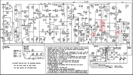
I noticed too on the schematics that there are two diodes next to where P5 is located but I cannot locate them on the amplifier.
Again, I would appreciate it if any of you can help me with this.
Have included some photos which should help illustrate what I am (trying to) explain.
Thanks
Pot P5 has a component that is linked from one of its terminals to the resistor R54. It looks like a resistor with the colours red, black, brown, and white on the body which doesn’t seem to relate to anything as far as I can see. It looks very similar to C31, a capacitor shown on the circuit diagram.
I found (on one attempt) that with the resistance turned right down on p5 the fuse held but when I turned it up slightly it blew. Resistor R54 is ok, which makes me suspect that the component linked R54 and P5.
I noticed too on the schematics that there are two diodes next to where P5 is located but I cannot locate them on the amplifier.
Again, I would appreciate it if any of you can help me with this.
Have included some photos which should help illustrate what I am (trying to) explain.
Thanks
Attachments
Also the LARGEST PHYSICAL SIZE. Modern resistors have high power in smaller packages but they do this by running HOT. Physics says he bigger the package for a given power, the lower the temperature on the surface.Those and the ones with painted on codes may indeed be wirewounds.
I would use the highest power rating for the new resistors that will fit the pcb properly.
And mount them high OFF the PCB (like the originals) so they don't burn it Old phenolic PCBs are easily charred.
Check the working channel for the diodes. They should be on the heatsink and connected to points J & C (I think) on the PCB. If they are missing / not connected, someone has really botched the amp. The diodes & P5 set the bias for the output stage. If no diodes, the output stage will runaway, blow fuses and/or die. Which fits in with what you've found.I noticed too on the schematics that there are two diodes next to where P5 is located but I cannot locate them on the amplifier.
Pot P5 has a component that is linked from one of its terminals to the resistor R54. It looks like a resistor with the colours red, black, brown, and white on the body which doesn’t seem to relate to anything as far as I can see. It looks very similar to C31, a capacitor shown on the circuit diagram.
The extra capacitor is probably a naive, yucky attempt to cure instability or implement Cherry compensation. Remove it.
Ted Ashley, who designed the LEAK Stereo 30 plus said it was a mistake to use plug-in boards. They were unreliable. So check and clean the connections and the PCB where they plug in. If the connection to the diodes on the heatsink is unreliable, that could also give your symptoms.

Yes, I've noticed that for some Vishay resistors that I tried recently. Not good, I want BIG resistors.Also the LARGEST PHYSICAL SIZE. Modern resistors have high power in smaller packages but they do this by running HOT. Physics says he bigger the package for a given power, the lower the temperature on the surface.
And mount them high OFF the PCB (like the originals) so they don't burn it Old phenolic PCBs are easily charred.
Yes, even heavily gold-plated fingers will gives problems after a while.Ted Ashley, who designed the LEAK Stereo 30 plus said it was a mistake to use plug-in boards. They were unreliable. So check and clean the connections and the PCB where they plug in. If the connection to the diodes on the heatsink is unreliable, that could also give your symptoms.
The extra bodged on component is just a capacitor, and unless it's S/C won't cause any problems - you could always disconnect it as it's not even shown on the circuit.Still have not managed to get this channel working. The problem is that it blows the 1.5 fuse each time it’s powered up. Every suspect component on the board has now been checked/replaced except for a couple of components that I’m having difficulty recognising, and pretty sure that one of them is the problem.
Pot P5 has a component that is linked from one of its terminals to the resistor R54. It looks like a resistor with the colours red, black, brown, and white on the body which doesn’t seem to relate to anything as far as I can see. It looks very similar to C31, a capacitor shown on the circuit diagram.
I found (on one attempt) that with the resistance turned right down on p5 the fuse held but when I turned it up slightly it blew. Resistor R54 is ok, which makes me suspect that the component linked R54 and P5.
I noticed too on the schematics that there are two diodes next to where P5 is located but I cannot locate them on the amplifier.
Again, I would appreciate it if any of you can help me with this.
Have included some photos which should help illustrate what I am (trying to) explain.
Thanks
I would suggest you short the bases of T8 and T9 (the drivers) together, this sets the quiescent current to zero, and removes any possible issues with the bias components - if the amp then works (although it will have crossover distortion at low volume), then the fault has got to be in the bias components. Most likely option would be a dodgy pot, as this rather 'nasty' bias circuit sets the bias to 'suicide point' if the pot fails, or one of the diodes.
The pot is easy to change, usually not so the diodes (as they are normally special bias diodes), personally I'd much prefer a Vbe multiplier for the bias, connected so if the pot fails the bias decreases.
Thanks Nigel. I tried asyou suggested, shorting the bases of t8 and t9 but made no difference.The extra bodged on component is just a capacitor, and unless it's S/C won't cause any problems - you could always disconnect it as it's not even shown on the circuit.
I would suggest you short the bases of T8 and T9 (the drivers) together, this sets the quiescent current to zero, and removes any possible issues with the bias components - if the amp then works (although it will have crossover distortion at low volume), then the fault has got to be in the bias components. Most likely option would be a dodgy pot, as this rather 'nasty' bias circuit sets the bias to 'suicide point' if the pot fails, or one of the diodes.
The pot is easy to change, usually not so the diodes (as they are normally special bias diodes), personally I'd much prefer a Vbe multiplier for the bias, connected so if the pot fails the bias decreases.
Thanks. I managed to locate the diodes on the heatsink and they all measure ok.Check the working channel for the diodes. They should be on the heatsink and connected to points J & C (I think) on the PCB. If they are missing / not connected, someone has really botched the amp. The diodes & P5 set the bias for the output stage. If no diodes, the output stage will runaway, blow fuses and/or die. Which fits in with what you've found.
The extra capacitor is probably a naive, yucky attempt to cure instability or implement Cherry compensation. Remove it.
- Home
- Amplifiers
- Solid State
- Leak Stereo 30 plus resistors