
Just saw this. When I tried the CM I didn't remove the Riv and Civ from the Miro pcb. It still worked.A word of warning for those building the XEN CM IV and using DIP8 plug-ins, like Paddy and Ripster did.
You MUST remove Riv and Civ from the miro board, and you must solder (SMD) Riv and Civ on the XEN boards.
It is NOT plug and play swap for DIP8 opamps.
If you want to go back to opamps later, you need to reinstall Riv and Civ on the miro board.
Patrick
What happened. Did I bypass the CM ?!
For those who are going to try other output stages like Patricks current mirror, or valve output stages, or pedja rogic diamond buffer and so on.... I would strongly recommend that you socket the Riv at least. Civ is not quite as easy because it is surface mount and underneath the board, but maybe still with a little adapter it might be possible. That way you can remove/add them as you see fit.
Personally, I installed opamp sockets for the opamps, and then just use some dip pins to go into pins 2 and 3. You can make little adapter boards etc if you like for different kinds of resistors, melf, SMT, and so on. That will allow you to try other stages where the Riv and Civ (if used) are away from the DAC board.
Personally, I installed opamp sockets for the opamps, and then just use some dip pins to go into pins 2 and 3. You can make little adapter boards etc if you like for different kinds of resistors, melf, SMT, and so on. That will allow you to try other stages where the Riv and Civ (if used) are away from the DAC board.
Hi guys!
How bad/ok is to put the DAC into the same case with Class D amplifier? Will SMPS add make high frequency noise or I can isolate it?
I know it's not 100% related to the theme, but many of you've built the DAC and how did you do it?
Separated case for the DAC?I just want my girlfriend wants to do it in minimalism style.
How bad/ok is to put the DAC into the same case with Class D amplifier? Will SMPS add make high frequency noise or I can isolate it?
I know it's not 100% related to the theme, but many of you've built the DAC and how did you do it?
Separated case for the DAC?
Do it minimalist...isolate the girlfriend 😉
If you use toroids, it should be ok Put it far the outputamp coils of the amp if using the same case. Put it far of the nude smps little traffos too.
If you use toroids, it should be ok Put it far the outputamp coils of the amp if using the same case. Put it far of the nude smps little traffos too.
For those who are going to try other output stages like Patricks current mirror, or valve output stages, or pedja rogic diamond buffer and so on.... I would strongly recommend that you socket the Riv at least. Civ is not quite as easy because it is surface mount and underneath the board, but maybe still with a little adapter it might be possible. That way you can remove/add them as you see fit.
Personally, I installed opamp sockets for the opamps, and then just use some dip pins to go into pins 2 and 3. You can make little adapter boards etc if you like for different kinds of resistors, melf, SMT, and so on. That will allow you to try other stages where the Riv and Civ (if used) are away from the DAC board.
you can experiment with ferous material wall to split the area. ferous material catch a part of the radiation and disipate it. Copper or Mu metal act more as a shield. Of course as the enclosure are often in metal in our hifis, they have indeed a role. And in EC, EMI radiation is very reglemented, boxes must have poor radiations in order not to polute close electronic devices... My basic understanding anyway is this is a specialist affair that ask Huuuuuge expensive tools and proper labotary to control it...way above enthusiast tools. What happen inside the box is more a jungle and you can often see SMPS shielding inside good amps that use that power technologie.
As says Fran, you will need to trust your ears !
Well, off topic, sorry.
As says Fran, you will need to trust your ears !
Well, off topic, sorry.
In "all-in-one" devices are most problems caused by bad GND wiring 🤣
Lol...
I do not care I just use a 1985 Sony walkmann with its orange foams on the headphone and only have ten cassettes. 🤣👍
I do not care I just use a 1985 Sony walkmann with its orange foams on the headphone and only have ten cassettes. 🤣👍
Thanks to Miro for the design and #jimk04 for sending me the boards. Finally put them into a chassis.
Modified to accept stacked AD844. Trimmers on the AD844 to null out the dc offsets to negligible value.
I had the opa627 installed initially and find it sounding lack of spatial quality in complex music. sounded flat and two dimensional. Installed a single AD844, well was better but not good enough. Stacking 3 of them, and wow...... i think it is the way for me. Currently taking the output from the buffered output of the AD844. I will experiment with taking the non-buffered output and connect them to an external buffer next.
very practicalI had the opa627 installed initially and find it sounding lack of spatial quality in complex music. sounded flat and two dimensional. Installed a single AD844, well was better but not good enough. Stacking 3 of them, and wow...... i think it is the way for me. Currently taking the output from the buffered output of the AD844. I will experiment with taking the non-buffered output and connect them to an external buffer next.
could you please tell where did you connect trimmer to ad844 to null DC offset
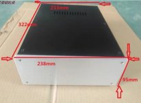
@commstech can you please write the size of your case for boards? I also looking a spacious case.
Attachments
- Home
- Source & Line
- Digital Line Level
- DAC AD1862: Almost THT, I2S input, NOS, R-2R