If I see correcly, the heatsink lies flat on the other side of the circuitboard. Then there are gaps for the transistors. So, cut some pieces of metal the size of the gap, but slightly thicker than the circuit board. Drill a hole in the pieces for the mounting screw. Now mount your larger transistor (not to3 of course) as usual, with the pieces of metal between the transistor and heatsink. You will have to bend the legs of the transistor a bit obviously to fit to the soldering pads.How will you mount it?
There are still easy ways to screw that up. Good thermal contact on both surfaces requires more than a hacksaw to make the required metal shims.
You need lapped metal shims.
Better would be the EEK!! way...😱
Just mount the (bigger / awkward to fit) transistors on big heat sinks, attach to the frame, run long wires to the PCB.
It will look odd, but if you do it properly, it will never break.
And who is going to look inside?
And if you blow something up, don't tell anybody, just dispose of the dead body.
Last edited:
Hey, this is diyaudio, right? but you have to feel confident about it, otherwise it is of course better to get suitable to220 parts.There are still easy ways to screw that up. Good thermal contact on both surfaces requires more than a hacksaw to make the required metal shims.
😆And if you blow something up, don't tell anybody, just dispose of the dead body.
Unfortunately, the proper solution WENT AWAY.Hey, this is diyaudio, right? but you have to feel confident about it, otherwise it is of course better to get suitable to220 parts.
Attachments
Angie grinder makes just as much of a mess as a hacksaw. Better to use a dremel on the PCB, assuming that you dont accidentally destroy something.Takes too much time, use an angle grinder
My original question was: how will you fit a device with a large hole in a place with a small hole? The larger transistor may have a bigger mounting hole.
If the much higher rated transistor above is actually available, that is the best solution.
My suggestion was more practical than putting shims near live tracks.
I sometimes have to do high grade polish, shims have to have prefect fitting, or the heat conduction goes down drastically.
Putting the larger parts on a separate heat sink, if the higher rated ones are not available, is safer than using a dremel tool on fairly hard to replace PCB.
Someone who doesn’t have a Dremel and can use it carefully enough to hog out the board probably doesn’t have the machine shop tools and skill needed to make a flat enough shim either. Either is equally difficult. One requires more expensive toys.
Mount ‘em to a large flat surface on the other side of the board. Put heat shrink on the leads. Run the wires thru the holes in the board. It’s a kluge. How much do you trust it not to come loose in 10 years? Is it worth this much trouble if the outputs that are in there are still working?
Mount ‘em to a large flat surface on the other side of the board. Put heat shrink on the leads. Run the wires thru the holes in the board. It’s a kluge. How much do you trust it not to come loose in 10 years? Is it worth this much trouble if the outputs that are in there are still working?
Actually a good idea. Didn't think of that, because I don't have a dremel. Or use the angle grinder on the PCB 😬Angie grinder makes just as much of a mess as a hacksaw. Better to use a dremel on the PCB, assuming that you dont accidentally destroy something.
What it takes is the proper (very small) grinder attachment for the dremel. I wouldn’t even try unless you had the right tool.
Just drill the small hole big enough. About the heat conduction, use thermal grease.My original question was: how will you fit a device with a large hole in a place with a small hole? The larger transistor may have a bigger mounting hole.
If the much higher rated transistor above is actually available, that is the best solution.
My suggestion was more practical than putting shims near live tracks.
I sometimes have to do high grade polish, shims have to have prefect fitting, or the heat conduction goes down drastically.
Putting the larger parts on a separate heat sink, if the higher rated ones are not available, is safer than using a dremel tool on fairly hard to replace PCB.
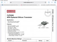
But my first choice would be to get BD203 and BD204 transistors for 40 cents each.
hello!
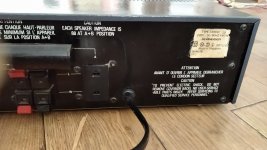
I bought this amplifier ( hifi sound project 6691), I opened it to clean it and I found that the final transistors are changed. Or pair are TIP41c+TIP42C and other A768+C1826. I don't know what transistors were originally.
Under "hifi sound project 6691" there isn't to find a serv. manual. If you find out the associated model No from Philips or Loewe, there it is probably more easy to find this manual and thus you will find out the genuine used transistors for the power output stage.I found out that this device is made by Philips and sold under several brands: Loewe, Schneider, Dueux. It doesn't sound bad, but I think it would be better in the initial configuration. Maybe anyone knows about this project, or if not, please tell me what would be the best transistor for this configuration. I don't know what voltage comes out of the transformer, the filtering capacitors of the source are 35V. I'm not an electronics specialist, I only have basic knowledge.
Thanks.
It was made in Singapore, so the Sanken transistors are the original ones.
Replacing with a higher rated transistor will simply make it more robust, as JMF said, the voltage and the supply decide the power output.
But the rest needs to be checked out, the TIP used are not terrible either.
Could be leaky capacitors for example, the unit is quite old.
Replacing with a higher rated transistor will simply make it more robust, as JMF said, the voltage and the supply decide the power output.
But the rest needs to be checked out, the TIP used are not terrible either.
Could be leaky capacitors for example, the unit is quite old.
Loudness? One channel is louder than the other?...at high volume there is a difference in power.
Most likely, this difference in loudness that you hear, is because the stereo volume potentiometer is imperfect.
A "stereo" potentiometer is actually two separate potentiometers, both mounted on one common shaft. Because of manufacturing tolerances, the two pots may not "track" perfectly - meaning that the output from one of them may be louder than the other one at some settings of the knob.
Since your amplifier has a balance control, the simplest solution is to simply adjust the balance when you turn up the volume high enough to hear that left-right channel imbalance.
-Gnobuddy
The bigger device still has to conduct heat to the smaller area on the PCB, intended for the smaller device, and that will cause a bottle neck of sorts, like putting too small a radiator hose...the heat flow will not be proper.
Angle grinder on a PCB?
That is simply too big and unwieldy.
Also it seems you have never used one, you have no idea how to use it on a fine gap.
Thermal grease needs to fill gaps between reasonably flat surfaces, so burrs and so on are not allowed.
Again, your idea was not practical.
Remember that using an abrasive machine on a PCB will send conductive particles flying all over.
For safety, that means removing the board from the body, doing the work elsewhere, and then cleaning it of every tiny bit of copper, and the risk of something going bang if you miss just one little bit.
Tedious, and risky.
Need I call your suggestions impractical, or expand further?
Last edited:
I will try to answer everyone here. This is the model in the photo and I did not find the service manual, so I asked your opinion. As I said, the sound is good, better than the last old amplifier I had, a Sony from the 80's with STK (I don't know the exact model because I sold it about 2 years ago).
They are not leaking capacitors, are all Nippon Chemi-Con.
There are solutions for mounting the 2SC5200-Toshiba, just lifting the heatsink by a few mm, but I won't do it yet. I will follow your advice and wg_ski's electronics lesson.
If the discussion was extended, I would have 2 more questions:
1. Why at the same gradation on the potentiometer the sound power is much higher on the radio than on the "Tape" input that I use as an auxiliary? I use DAC (ES9023 and PCM5102) which output 1V rms per channel.
2. Can you tell in which class the A or AB amplifier works?
Attachments

- Home
- Amplifiers
- Solid State
- Final transistor for vintage receiver