Hi, I got a stereo tube amplifier for repair. 2x(4xEL84). Some sparks of tension has taken place, burned places on the circuitboard. I have measured the output transformer for self-induction and now it appears that they show about 30% deviation. From anode to anode, one is 6.8H the other is 4.2H. Is this normal ? or is one transformer gone ?
If the lower inductance transformer relates to the suspect channel, it most probably has suffered from arcing between adjacent layers and needs to be replaced.
Best regards!
Best regards!
Measuring inductance is tricky, and that value seems to be low for an OPT. I would try first measuring the turn ratio, then from there you get the impedance ratio. Do you have the original data for the transformer?
Sorry, I don't have any data of these transformers. I will measure the ratio of both transformers.Measuring inductance is tricky, and that value seems to be low for an OPT. I would try first measuring the turn ratio, then from there you get the impedance ratio. Do you have the original data for the transformer?
When I measure the inductance of a transformer (primairy) with open secondary and when I short circuit the secondary the primairy inductance disappears this will tell you that there is no short in the transformer ?? Both transformers do this!
Do you mean impedance?Sorry, I don't have any data of these transformers. I will measure the ratio of both transformers.
When I measure the inductance of a transformer (primairy) with open secondary and when I short circuit the secondary the primairy inductance disappears this will tell you that there is no short in the transformer ?? Both transformers do this!
For a 4xEL84 PP I would expect something like 4K~5K OPTs, but of course that's not set in stone. What's B+ voltage?
cheap multi meters use like 500Hz often rectangular signals of some 100mV amplitude to estimate inductance;Hi, I got a stereo tube amplifier for repair. 2x(4xEL84). Some sparks of tension has taken place, burned places on the circuitboard. I have measured the output transformer for self-induction and now it appears that they show about 30% deviation. From anode to anode, one is 6.8H the other is 4.2H. Is this normal ? or is one transformer gone ?
example:
if I measure a dozen brand new line transforners with that meter I get numbers between 6H and 12H ... so not necessarily indicating any one is defective.
inductance increases with higher excitation and decreases with rising frequency;
if I measure the same transformers at 50Hz and 230V signal they come out as 50H.
Shorting secondary you measured the leakage inductance (few or few ten mH).
Instead of it try to measure primary DCR of both transformers with appropriate LCR measuring device.
If the "bad" transformer has primary shorting, the DCR will be different.
Instead of it try to measure primary DCR of both transformers with appropriate LCR measuring device.
If the "bad" transformer has primary shorting, the DCR will be different.
The inductance is low for both , maybe the meter can't measure corectly
If you want to be absolutely sure you can put the primary at mains voltage like a power transformer . Then you can check if secondary voltages are the same , if it heats up or something is wrong
If you want to be absolutely sure you can put the primary at mains voltage like a power transformer . Then you can check if secondary voltages are the same , if it heats up or something is wrong
The B+ voltage is 440 volts, the ratio 14,68 at 16 ohms so the RAA is about 3K5. I did the inductance measurement with a real inductance meter. I will do this again with another one tomorrow
440V with EL84? That's some serious overclocking 🙂The B+ voltage is 440 volts, the ratio 14,68 at 16 ohms so the RAA is about 3K5. I did the inductance measurement with a real inductance meter. I will do this again with another one tomorrow
I measured the inductance with another device and the result was the same. I measured some other voltages in the amp. The G1's of the EL84 are on -16 volts. So I think this amp is in class B and then it is possible to give the tube a higher anode voltage. So the question remains: is it normal that 2 of the same output transformers have a so great difference in induction? and why? Because the test for the ratio (12 volts ac 50Hz on 16 ohm) give the same ratio results for both transformers.
Th DCR of both transformers have the same value (mid to A upper 71.2 ohms mid to A lower 57,1 ohms)
Th DCR of both transformers have the same value (mid to A upper 71.2 ohms mid to A lower 57,1 ohms)
Last edited:
If the DCR is the same, the the sorting does not occur.
It doesn't matter the core type, if one transformer squeezing different from the other.
The inductance may vary if the fastening loosed.
It doesn't matter the core type, if one transformer squeezing different from the other.
The inductance may vary if the fastening loosed.
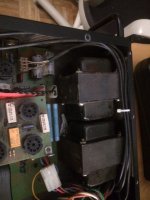
It's an E+I coreWhat core it has , double C , E + I ?
Attachments
Connect the primaries of each transformer, one after the other, via a light bulb and a AC mA meter to your AC mains, even better via an isolation transformer, and compare the meter readings.
Best regards!
Best regards!
I will do that. The findings you will find here. Thanks
Both transformers via an isolation transformer and a series lightbulb give me the same result as 11.07 mA. So can I say that my outputransformers are ok?
I think yes.
Both transformers via an isolation transformer and a series lightbulb give me the same result as 11.07 mA. So can I say that my outputransformers are ok?
I think yes.
Last edited:
Thats than about 75H at 50Hz and that looks ok. My induction meter measures at a much higher frequency.
I think I am missing something on the mains posts above... an output transformer is out of phase and would not give you information on each side of the primary.The inductance is low for both , maybe the meter can't measure corectly
If you want to be absolutely sure you can put the primary at mains voltage like a power transformer . Then you can check if secondary voltages are the same , if it heats up or something is wrong
You could run a small ac voltage to the output (a few volts) winding and look for reasonable and matching high voltage (remember it will be stepping up a good bit!) on each side of the primary from the center tap. I think that's a more reasonable approach. That or just try it out and measure in circuit.
The mains would be connected from anode to anode , you don't use the central tap ... tests can be done in many ways , this is simple and you don't need anything
For transformers you should use 50Hz ... otherwise the LRC bridge is fooled by parasitic capacitance , hysteresis and so onThats than about 75H at 50Hz and that looks ok. My induction meter measures at a much higher frequency.
- Home
- Amplifiers
- Tubes / Valves
- PP output transformer