if you made measurements with contact meter, then you're good
dunno what's temperature in your room now, but - say that you have plenty of time to replace L bracket 'till Summer
though, it's easier now, while everything is still in pieces
dunno what's temperature in your room now, but - say that you have plenty of time to replace L bracket 'till Summer
though, it's easier now, while everything is still in pieces
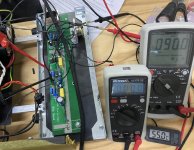
Sad news to report. During first period of running in amp, it blew a fuse after about 6 hours of playing and since this is test mule with Antek 3218, I only put in 2.5A fuse (2.5x120V = 300W). No big deal. I changed to 3A fuse and it was playing again for about 1 hour and blew again. Changed to 4A fuse and either I wasn't waiting long enough to drain caps or it just was already on way to Ge-drekland. Went back to front end (FE) and output section (OS) testing, FE was still fine but OS was 50% THD. I changed active parts (817, 385, 139/140) thinking the mosfets were sturdy fellows but still no good. Pulled IRF9510 and put on tester, tested ok so only conclusion was Ge. I swapped 22R back in for R122, plugged 2SA1943 and everything is good again in that channel. Has to be 2N1099 slowly turned itself into a jumper wire. Id was set at 1A but after it went bad, on the bench supply, it was pulling 2A (limiter) on both rails.
I will take this opportunity to test 2N277 (Delco) as I found datasheet which is different spec from the Motorola 2N277 and looks like it might survive.
Also found perfect fit mica sheet mica sheet for 2N1099
I will take this opportunity to test 2N277 (Delco) as I found datasheet which is different spec from the Motorola 2N277 and looks like it might survive.
Also found perfect fit mica sheet mica sheet for 2N1099
Attachments
I had popcorn episodes with some (NOS) Russkie 1T813, but all I tried of my (NOS) 2N1099 worked flawlessly
be careful - insert fuses in rails (say 2A5) as long you're playing with - when Russkie gone Dodo, it took big mosfet too
dunno how
though, Russkie was gone on first smidge of signal modulation, not gracefully as yours
dunno how
though, Russkie was gone on first smidge of signal modulation, not gracefully as yours
OT for comforting tormented souls: a possible reason why certain members are asking awkward questions (make sure subtitles are enabled!):


Stephen,
Really sorry you had a 2n1099 fail on you. 🙁
Thanks for posting the datasheets. It's interesting that the Delco gives a max junction-to-case thermal resistance of 0.8C/W while the Motorola one is given as max 0.5C/W. And it seems the Motorola one gives a higher max junction operating temp as well.
Dennis

Dennis
Looks fantastic !!!!

Thanks guys. Hopefully I can try powering up a channel this weekend.
BTW, where are you taking the speaker return from? I'm thinking of just from that row of holes connected to GND.
Dennis
BTW, where are you taking the speaker return from? I'm thinking of just from that row of holes connected to GND.
Dennis
exactly
if you're Cheapskate as Papa is ( and I become of recently), it'll save you some wire length
beside that, it'll include some modulation (across speaker power line) in NFB route
if you're Cheapskate as Papa is ( and I become of recently), it'll save you some wire length
beside that, it'll include some modulation (across speaker power line) in NFB route
 which is ( NFB) nonexistent, but who cares - when you write is as that, it just sounds Posh
 Just noticed something: In post #411 by myleftear, is it possible the Cinemag transformer is on backward?
https://www.diyaudio.com/community/threads/old-soul.370744/page-21#post-6914960
The holes for Pins 2-5 for cinemag goes are near the edge of the pcbs and in the case of the transfomers I have,
those pins are on the side with the red letter labeling.
https://www.diyaudio.com/community/threads/old-soul.370744/page-21#post-6914960
The holes for Pins 2-5 for cinemag goes are near the edge of the pcbs and in the case of the transfomers I have,
those pins are on the side with the red letter labeling.
good catch!!
though, in case of Cinemag - it is definitely quadrifillar wound, no difference
and - I'm not sure that label is always on primary side
in newest pcbs ( for all autoformer amps) I did include Full Monty Cinemag pinout, so no need for clipping pins
though, in case of Cinemag - it is definitely quadrifillar wound, no difference
and - I'm not sure that label is always on primary side
in newest pcbs ( for all autoformer amps) I did include Full Monty Cinemag pinout, so no need for clipping pins
- Home
- Amplifiers
- Pass Labs
- Old Soul