Hi all,
New here, just found this forum after googling my amp!
Got my PM44SE out of the loft today. Like an idiot I rigged it up and switched it on without considering that it may damp. I thought I heard a thud when I was out of the room.
Tried to play the CD player, all LEDs are on and internal fuse is ok but no sound. It usually clicks about five seconds after switch on which it isn't doing now. There was the smell of burnt dust after I turned it on the first time. It did a similar thing once efore after it had been in storage but I think that was the fuse. The solder side of the centre board looks brown on both edges near the centre. The board is still getting warm. I'm not big on electronics but am a service engineer on catering equipment and do deal with pcbs so am willing to give this a go, could do with some guidance if anyone has schematics or knowledge of this unit.
Thanks in advance.
This is odd...bump 12 years later
Hi all,
Having forgotten all about joining or posting here twelve (!) years ago, I found my way back here after asking a local TV repair guy to look at the above amp this year, he attempted to repair it and then gave up on it after several components he replaced failed straight away. I ended up back here by chance and then was alerted (after trying to register) that i already had an account, so I reset my password and logged in to find I'd already posted this thread years ago. Life diverted me from hifi for that time and and now it's back on.
I've attached the diagram for it. The guy replaced Q751, Q761, Q763, R767 x 2, R773, Q801, Q753, Q755 and IC Q705.
He seems to think that the twin resistors at R767 have blown, but my multimeter suggests their resistance is correct at about 2 ohms, but they are immediately glowing red and smoking when the unit powers on. I don't have a bulb rig-up at the moment so will need to get one sorted before tinkering with this. My multimeter suggests new transistor Q763 has a dead short between all connections, and the only one of the four transistors giving consistent resistance readings between b/c & b/e (taking b as on the left hand side as looking at it with connections at the bottom, c in the centre and e on the right as per attached diagram and attached datasheet for replacement A1265Ns) is Q764 with about 6/7 between b/c and b/e (black/common/negative on the b and meter set to 20m).Q762 seems to be open circuit between b/c, 6/7 b/e. Q761 is open circuit b/e, 8 b/c. I don't know if these being still connected to the board will affect their readings if there are faults elsewhere
As he's already replaced the integrated circuit I'm wondering what the root cause could be, the output from the transformer is correct at about 29V each side. Any thoughts from experienced folk here would be greatly appreciated.
Thanks in advance.
Attachments
........is only one channel bad , or both?
the emitter res R767 are 0,18 ohms - not 2ohm.......
if these run hot:
the bias current ist too high or
(output)transistors are dead....
if one channel is working you can compare the measurings
of the two channels (measure the parts with your multimeter).
the emitter res R767 are 0,18 ohms - not 2ohm.......
if these run hot:
the bias current ist too high or
(output)transistors are dead....
if one channel is working you can compare the measurings
of the two channels (measure the parts with your multimeter).
Thanks. Sorry my mistake, I meant about 0.2 not 2 re R767, my multimeter only goes to 1 decimal place on the 200 setting but it's 0.1/0.2 above zero between the probes on both. The guy who attempted the repair thinks something is blowing these if they have indeed failed. I mentioned the bias but his view was he wouldn't have expected such a smoky immediate failure just from those, but I don't know. Unfortunately it's both channels, no sound at all. I thought he'd replaced the Q751 & Q752 which I think are the bias transistors, but they're not on his list. I'm getting readings between b/e & b/c on both, the only thing I know is definitely dead is the one new transistor with two of the others in doubt. It's which happened first that I'm trying to puzzle out, but I think I'll have to get some parts and try them, and set it up with the dim bulb rig.
If you're serious about fixing the amp, don't apply mains power without a lamp limiter.
You'll need to keep it in series with the amp until the issue is diagnosed/resolved (the amp will function with a 60W bulb...).
Here's my cheap Screwfix limiter (I already had the 60W bulb and crocodile clips).
20211126_Limiter.jpg
Check Q751-Q764 (7x transistors/side - 3x transistors on the heatsink + 4x transistors adjacent to the heatsink for short/open circuits, etc.
N.B. Q751 & Q752 are Darlingtons!
20211126_Transistors_boxed.jpg
Remove F901 (T1.6A) and attach the bulb to the fuse clips.
20211126_Marantz_F901.jpg
Disconnect ALL peripheral equipment and speakers and set the Volume control to minimum.
Also turn the bias pots fully-anti-clockwise (R755 & R756).
Apply power (via the bulb limiter).
If the 60W bulb lights-up when power is applied, remove power and seek further advice.
Never attempt to power-up the amp with the PCB out of the chassis - Marantz use the heatsinks and chassis to connect the various ground strips on the PCB. More info....
Good Luck (with the initial diagnosis)!
Attachments


Last edited:
Thanks Hamish, that's really helpful. Lamp limiter was what I was referring to when I said 'dim bulb rig' so yes I can and will set that up easily and won't power the amp without it. It's completely disconnected from any other kit and just on the bench and will stay as such until if and when fixed. Obviously there's no point doing anything until I've replaced the transistor that I know is dead so I'll order that and a few other suspect bits and extras and sort out the lamp limiter and check all those components. Thanks for the tip on Q751 & Q752!
Hi can you advise if you have removed the back panel and the four fixing screws securing the Amplifier main board to the chassis.
There is a common ground connection that must be made via the fixing screws
if you look at the speaker terminal fixing screws they ground to the chassis.
If the Amplifier is powered up during repair or testing with out the grounding connection being made it will result in the output stages(s) failing catastrophically.
The number one cause of failure with this series of Amplifier is dry joints form on the transistors mounted on the heat sink, the input protection fuse will blow.
But often the output transistors will fail.
Always check the emitter resistors and associated components in the output section that has failed.
Also only source genuine original devices there are a lot of fake and counterfeit transistors out there.
Ensure you set the output bias as detailed in the service manual typically 14 millivolts when measured across the Emitter resistor(s)
Repairing the Amplifier should be done with a systematic approach.
when repairing the main Amplifier board look for and reflow other suspect dry solder joints you will see discoloration of the solder joints and cracking where components run hot.
The speaker protection relay should also be replaced as the switching contacts will be oxidised this will avoid any issue with intermittent Audio loss or distortion at low volume.
I would also check and resolder the input RCA sockets as there will be dry joints.
Also check and resolder the head Phones socket and balance control again often dry joints will be found.
The input lection switch can be removed the board and taken apart, the contact slide rails can be cleaned with a fibre glass pencil there will be a lot of oxidisation.
Also clean the switches and volume control potentiometer with a high quality switch cleaner for example De-Oxit.
Hi & thanks for such an informative reply. Was that your video Hamish posted? Really helpful if so!
I certainly haven't run it with the screws out, as I was previously aware of the protection circuit and had wondered if it was in protection mode. I'd seriously hope the chap who tried to help me out hadn't done so either, but I'm not going to ask him now. I had thought about whether the relay and protection IC should be replaced. I can't seem to find a reputable source for the 24V 24SMBU-522 or any reliable suggestion for an alternative, would you happen to know which to use in its place?
I'm going to take onboard all of your other recommendations (re dry joints and cleaning components especially) and take my time with a methodical approach, it's been out of action for over 12 years so not much point rushing it now!
Thanks very much for taking the time to share your knowledge.
Hi The relay is package type G2R, you need to order one with a 24V DC coil and double pole single throw 5 Amp rating switching contacts.
For example Google Image Result
You can order a Double pole double throw version and cut off the unwanted pins.
Also check in the area of the protection circuit, to ensure
There is no dried brown glue covering the resistors and wire links.
If so it has to be removed and the resistors replaced.
For example Google Image Result
You can order a Double pole double throw version and cut off the unwanted pins.
Also check in the area of the protection circuit, to ensure
There is no dried brown glue covering the resistors and wire links.
If so it has to be removed and the resistors replaced.
Also check in the area of the protection circuit, to ensure
There is no dried brown glue covering the resistors and wire links.
If so it has to be removed and the resistors replaced.
Thanks I will do, and thanks for the relay info.
Hi all,
Having forgotten all about joining or posting here twelve (!) years ago, I found my way back here after asking a local TV repair guy to look at the above amp this year, he attempted to repair it and then gave up on it after several components he replaced failed straight away. I ended up back here by chance and then was alerted (after trying to register) that i already had an account, so I reset my password and logged in to find I'd already posted this thread years ago. Life diverted me from hifi for that time and and now it's back on.
I've attached the diagram for it. The guy replaced Q751, Q761, Q763, R767 x 2, R773, Q801, Q753, Q755 and IC Q705.
He seems to think that the twin resistors at R767 have blown, but my multimeter suggests their resistance is correct at about 2 ohms, but they are immediately glowing red and smoking when the unit powers on. I don't have a bulb rig-up at the moment so will need to get one sorted before tinkering with this. My multimeter suggests new transistor Q763 has a dead short between all connections, and the only one of the four transistors giving consistent resistance readings between b/c & b/e (taking b as on the left hand side as looking at it with connections at the bottom, c in the centre and e on the right as per attached diagram and attached datasheet for replacement A1265Ns) is Q764 with about 6/7 between b/c and b/e (black/common/negative on the b and meter set to 20m).Q762 seems to be open circuit between b/c, 6/7 b/e. Q761 is open circuit b/e, 8 b/c. I don't know if these being still connected to the board will affect their readings if there are faults elsewhere
As he's already replaced the integrated circuit I'm wondering what the root cause could be, the output from the transformer is correct at about 29V each side. Any thoughts from experienced folk here would be greatly appreciated.
Thanks in advance.
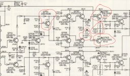
Have a look at the snapshot I attached.
All transistors 701 - 763 should be carefully checked and confirmed to be good working
D701 and D703 are also as important in getting the correct DC conditions for Q761 - R767 - Q763. These parts (the Q761 - R767 - Q763) shorted the V+ and V - rails, hence the catastrophic failure. This happened because Q761 and Q763 were fully open and conducting full current.
What I do not understand is why the R773 did not go open circuit... It should have - it's a safety resistor (you see, a designer did a good job here... but the part failed... maybe because of the combination of dirt and moisture accumulating around the resistor?? -> Please post some pictures, well-lit, high-res, in-focus 🙂 )
Once all the parts have been carefully checked, all resistors carefully checked, all solder joints & tracks are confirmed to be sound, you must use the following:
Signal generator outputting sinewave at some 1kHz at some 100mV, Variac and dual-channel oscilloscope. One channel monitors the input signal, the other monitors the output signal (at speakers terminals). Volume pot at full. Start increasing the AC slowly using a variac, pay close attention to the output signal. You should see a slow increase in amplitude, as you increase the AC, but the tops of each half of the sinewave will be (should be!) clipped SIMMETRICALLY. There should also be NO ringing superimposed on 1kHz sinewave. If you see unsymmetrical clipping or ringing, STOP and correct the fault.
Once all sweet, the output amplified sinewave should be symmetrically increasing around 0 (zero), AND the amount of clipping should be reducing slowly and symmetrically as you increase AC, until it is a nice, undistorted (unclipped), amplified sinewave of the original 100mV signal.
NOTE: you'll need to bypass the output relay and potentially, you may have to only supply the DC rails straight to the PCB that is faulty, this should not be that much of an issue really.
Do not load the output.
Attachments
Last edited:
...My multimeter suggests new transistor Q763 has a dead short between all connections, and the only one of the four transistors giving consistent resistance readings between b/c & b/e (taking b as on the left hand side as looking at it with connections at the bottom, c in the centre and e on the right as per attached diagram and attached datasheet for replacement A1265Ns) is Q764 with about 6/7 between b/c and b/e (black/common/negative on the b and meter set to 20m).Q762 seems to be open circuit between b/c, 6/7 b/e. Q761 is open circuit b/e, 8 b/c.
If your meter has a DIODE function/setting, use that instead of 20M Ohms range for measuring/testing semiconductor junctions (although a 'short' will always measure 0R regardless of the meter range setting). I seem to recall that my old Fluke measured semiconductor junctions on the 2k setting.
If you connect the BASES of Q753 & Q755 together (wire link), there should be ZERO current flow in Q757, Q759, Q761 & Q763 unless there's a duff transistor (or more) in that section. If you do this, measure the potential difference between the COLLECTOR & EMITTER of Q751 and between the EMITTER and 0V/GND.
Use the above component numbers +1 for the other channel.
Watch this to see what could potentially happen when Q751 or Q752 are turned off/fail/become disconnected from the PCB.
Good Luck!
Last edited:
Have a look at the snapshot I attached.
All transistors 701 - 763 should be carefully checked and confirmed to be good working
D701 and D703 are also as important in getting the correct DC conditions for Q761 - R767 - Q763. These parts (the Q761 - R767 - Q763) shorted the V+ and V - rails, hence the catastrophic failure. This happened because Q761 and Q763 were fully open and conducting full current.
What I do not understand is why the R773 did not go open circuit... It should have - it's a safety resistor (you see, a designer did a good job here... but the part failed... maybe because of the combination of dirt and moisture accumulating around the resistor?? -> Please post some pictures, well-lit, high-res, in-focus 🙂 )
Once all the parts have been carefully checked, all resistors carefully checked, all solder joints & tracks are confirmed to be sound, you must use the following:
Signal generator outputting sinewave at some 1kHz at some 100mV, Variac and dual-channel oscilloscope. One channel monitors the input signal, the other monitors the output signal (at speakers terminals). Volume pot at full. Start increasing the AC slowly using a variac, pay close attention to the output signal. You should see a slow increase in amplitude, as you increase the AC, but the tops of each half of the sinewave will be (should be!) clipped SIMMETRICALLY. There should also be NO ringing superimposed on 1kHz sinewave. If you see unsymmetrical clipping or ringing, STOP and correct the fault.
Once all sweet, the output amplified sinewave should be symmetrically increasing around 0 (zero), AND the amount of clipping should be reducing slowly and symmetrically as you increase AC, until it is a nice, undistorted (unclipped), amplified sinewave of the original 100mV signal.
NOTE: you'll need to bypass the output relay and potentially, you may have to only supply the DC rails straight to the PCB that is faulty, this should not be that much of an issue really.
Do not load the output.
Hi thanks for such a detailed reply and for highlighting the diagram for me like that. I don't have the equipment you've kindly given me instructions for using, to invest in it would cost more than buying a refurbished amp when combined with parts, but if I fall down the electronics rabbit hole here I might do it anyway!
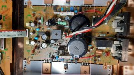
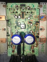
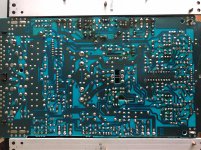
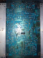
A lot of info here to work through and digest anyway, and I'm really grateful to you and everyone else sharing their experience and knowledge. I've attached a few photos as suggested. I've circled in red parts the guy listed as replacing and the blue mark on the seemingly failed transistor, but the other also has open circuit between base and collector (starting with negative on base). There looks like a lot of flux residue on the new connections to clean off. Thanks again.
Attachments
If your meter has a DIODE function/setting, use that instead of 20M Ohms range for measuring/testing semiconductor junctions (although a 'short' will always measure 0R regardless of the meter range setting). I seem to recall that my old Fluke measured semiconductor junctions on the 2k setting.
Good Luck!
Thanks, on the diode setting it's measuring half the resistance from base to both collector and emitter compared to the identical transistor on the other channel, on 200 it beeps (the others don't).
I'll set up a wire link later as you suggested, thanks for that info, and the video!
Hi thanks for such a detailed reply and for highlighting the diagram for me like that. I don't have the equipment you've kindly given me instructions for using, to invest in it would cost more than buying a refurbished amp when combined with parts, but if I fall down the electronics rabbit hole here I might do it anyway!
A lot of info here to work through and digest anyway, and I'm really grateful to you and everyone else sharing their experience and knowledge. I've attached a few photos as suggested. I've circled in red parts the guy listed as replacing and the blue mark on the seemingly failed transistor, but the other also has open circuit between base and collector (starting with negative on base). There looks like a lot of flux residue on the new connections to clean off. Thanks again.
I think he left out the two 120pF styrene caps. Not important for the DC conditions, but important nevertheless once the amp starts operating correctly, to ensure stable operation at all frequencies.
My suggestion to you is to try to find a fanatic who is going to be determined to get it going. 🙂
Working...mostly
I didn't get time to carry out every recommended action (yet) but I started with replacing the one transistor I knew was smoked (Q763) and then put the lamp limiter in series at the fuse holder, powered it and it went dim straight away. Relay clicked okay, so I tried a minidisc player through the headphones (which had also previously had no sound) and to my surprise I had full sound. I did my best to set the bias pots to 14mv but could only get close as the pots are so sensitive to movement and very flimsy, so have about 16 on the left and 12 on the right. Then through the speakers the right channel was on and off and crackly, so I reflowed the speaker connections and retried it, initially it was the same but eventually the right was working same as the left, so there's obviously more to look at there but I'm currently just glad to get any sound out of at all after changing just one transistor. I will chase it further and carry out all the reflowing and cleaning as recommended, but for now I just wanted to thanks everyone who's replied here with advice, tips and links that have collectively given me the confidence to pursue it. Fantastic community here!
I didn't get time to carry out every recommended action (yet) but I started with replacing the one transistor I knew was smoked (Q763) and then put the lamp limiter in series at the fuse holder, powered it and it went dim straight away. Relay clicked okay, so I tried a minidisc player through the headphones (which had also previously had no sound) and to my surprise I had full sound. I did my best to set the bias pots to 14mv but could only get close as the pots are so sensitive to movement and very flimsy, so have about 16 on the left and 12 on the right. Then through the speakers the right channel was on and off and crackly, so I reflowed the speaker connections and retried it, initially it was the same but eventually the right was working same as the left, so there's obviously more to look at there but I'm currently just glad to get any sound out of at all after changing just one transistor. I will chase it further and carry out all the reflowing and cleaning as recommended, but for now I just wanted to thanks everyone who's replied here with advice, tips and links that have collectively given me the confidence to pursue it. Fantastic community here!
That great to hear, once the input selector switch has been cleaned as advised and the speaker protection relay replaced all being well you should have clear Audio.
- Home
- Amplifiers
- Solid State
- Marantz PM44SE