This is one that is not going to work methinks. It has had to many mistakes made along the way and if the PSU polarities really have been reversed then its game over I'm afraid.
We have some massive success stories on here but this isn't going to be one of them unfortunately 🙁
We have some massive success stories on here but this isn't going to be one of them unfortunately 🙁
Yes, I started more on the more, like the diagram of Mooly, but like I said before I had a not very pleasant sound on the HP ... I tried again with the lamp, and the sound was less loud , I then reversed the polarity and I had no more noise ... I redid the lanpe without lanpe, then tested to connect the mass to the power supply always with the lamp, then without it is there that it's hot...🙁
I will try to find an electronics engineer near me, I will keep you posted
I will try to find an electronics engineer near me, I will keep you posted
The QUAD405 is a nice amplifier (I really like my modified QUAD405-2) however I might suggest that you start with a simpler and less expensive kit? Once you master that then perhaps consider a more expensive project like the QUAD405.
Hopefully you can find someone close to you to help with the QUAD405.
Otherwise perhaps start with a lower cost kit and don't wire anything up until you have wiring diagrams that are drawn up and reviewed "ok" first. And then perhaps wire it up but don't turn it on until you have taken photographs that can be checked.

Reading and think about doing this a lot just unfortunately I am still educating myself better to do this.
@xamenoss, mind sharing where you got these board from?
Also see this, why it advertises for 75w instead of 100 w typically, any different components? Just curious.
Classic HIFI Stereo QUAD405 Power amplifier MJ15024 Base on QUAD 405 75W+75W With SPK protection|Amplifier| - AliExpress
@xamenoss, mind sharing where you got these board from?
Also see this, why it advertises for 75w instead of 100 w typically, any different components? Just curious.
Classic HIFI Stereo QUAD405 Power amplifier MJ15024 Base on QUAD 405 75W+75W With SPK protection|Amplifier| - AliExpress
It is because they have derated the transformer from 300VAt to 200VA, so it delivers both less voltage and less power. In fact it may only deliver 67W/Ch by that ratio. May have used lesser transistors and other components here and there too.
Ah, I see that 200va transformer used in description now. Thanks.
BTW, this particular vendor also carries this one looks like a 405, II version? Maybe?
Not affiliated with the vendor, it just happen to the only one listing these with speaker protection built in.
Finished QUAD405 Power amplifier Base on QUAD 405 amplifier KTD1047 100W+100W With speaker protection|power amplifier|amplifier powerfinished power amplifier - AliExpress
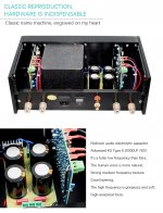
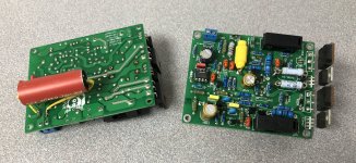
I don't see anything 405-II-like about it. Antique LM301 op-amp for example, which confirms my experience that these clones are all built on the first PCB version. Appears to have speaker relays, but any claimed 405 must have speaker protection of some kind, otherwise it isn't a 405.
The heat-sinking looks most inadequate. I don't know what 'new original' is supposed to mean, and 0.1% inductors are a waste of time in this circuit.
The heat-sinking looks most inadequate. I don't know what 'new original' is supposed to mean, and 0.1% inductors are a waste of time in this circuit.
I think there are four LJM Quad405-2 versions:
1. Metal TO-3 Version (LM301)
2. Plastic K D1047 Version (LM301)
3. Plastic K D1047 Quad405-2 Version (Ti TL071) (previous "latest")
4. Plastic ST 2SC5200 Quad405-2 Version (Ti TL071) (latest, new)
1. Metal TO-3 Version (LM301)
2. Plastic K D1047 Version (LM301)
3. Plastic K D1047 Quad405-2 Version (Ti TL071) (previous "latest")
4. Plastic ST 2SC5200 Quad405-2 Version (Ti TL071) (latest, new)
A lot of these clones seem not have speakers protection?but any claimed 405 must have speaker protection of some kind, otherwise it isn't a 405.
Attachments
I don't know how you concluded that. I can see the 10uF timing capacitor for the triac, just under the output connector.
I'd be more concerned about the 50V PSU capacitors, unless again they have derated the amplifier, so again it wouldn't really be a 405.
I'd be more concerned about the 50V PSU capacitors, unless again they have derated the amplifier, so again it wouldn't really be a 405.
I don’t have any EE background, just try to learn and guess as I go. I only have done some cap replacement on my vintage receiver, amplifier and very basic repair only. Have never put an amplifier together yet. That is why I am thinking getting a finished product and upgrade it just like recapping a vintage unit as my first phase then moving on to put the amplifier together from the scratch.
It is 2021, and I am truly amazed that people are discovering they can make Quad405 at home, simply amazing. But truly: the use of LM301 there is criminal, it has been only a quality amp for 2-3 years until much better came. Also, my design/layout was made from scratch, as I could not afford much board space, so it was 8x10cm board or something like that. Also, TO-218 power output transistors... duh, it makes zero sense to use the ugly expensive cans with bad heat transfer...Hi
I just got my LJM Quad 405 clone today.
Updated version
Earth problem is solved
Looks good
So many years and Quad 405 has proven itself as a good and interesting design, able to produce music with the worst quality components 😀 😀 😀. It's really sweet.
...next thing you will discover is that you can parallel the output transistors for greater power 😀
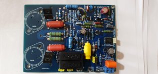
Sorry, sir, just opened the forum, this is my quad pictureDo you mean a "DIY kit"? If so there are a number of different QUAD405 kits and a number of different PCB sold online. If you post a picture of the kit (PCB and parts) that you have it would be easier to see if someone recognizes that particular kit and where to buy another. There are QUAD405 and QUAD405-2 kits, for example. Then there are multiple versions such as plastic package outputs or metal TO-3.
Attachments
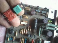
That isn't a kit as far as I can tell. That looks like a real QUAD405-2. (Based upon the surface mount current limiter module and the green transistors. (And the appearance of a number of other parts and the PCB.)
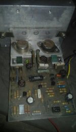
So are you looking to replace these boards, repair them, restore them, refurbish them or?
If looking for a reasonable low cost replacement there are the LJM QUAD405-2 with the 2SC5200 and TL071. Make sure your search includes the "-2" and the "2SC5200". That is the version I would buy if I was to buy new boards again. I would also replace the op-amp (later, after successfully installing and testing the stock board) with OPA134. I also have a habit now of replacing the power transistors on all such boards with genuine Toshiba 2SC5200 purchased from Mouser or Digikey (ONLY a real authorized distributor).
If you want to restore those boards there are others who might be better sources of information. (I have clones, I have never bought an original QUAD405.)
Two possibly useful links:
https://liquidaudio.com.au/quad-405-2-power-amplifier-restoration/
https://keith-snook.info/QUAD-405-2-Modification.html
Hello,
I have in the past built several QUAD405 kits.
The one in the picture is the best (LJM QUAD405-2). You just have to change the two power resistors, put a better input capacitor and change the chemicals (not mandatory). Of course if this kit is still delivered with correct components. I have seen the quality of the components of the kits drop for a few months.
Then it is good to remove TL071, put a socket and change the value of two components to setup the opamp gain for 1.5vRMS at input.
I no longer use it as I replaced it with a Q17. 😉
Regards,
Stef.
Attachments
Hello, I have just acquired two new version QUAD405-2 cards on the Alliexpress site and would like to modify the input gain. Could you provide me the value of the components you used for this modification. Thanks in advance
You have to change three components, not two. R6=100K, C4=150nF, R4=6k8. You can also do it by changing C1 and R3, with R4 still as above.
- Home
- Amplifiers
- Solid State
- QUAD 405 clone