In an ideal world I would, especially if series-wiring, but it's not always possible to get the volumes & tuning equal. JBL used dissimilar in one of their larger K2 or Everest models (I can't remember off-hand which), but that was a parallel wired job with large woofers rather than normal midbass units so a slightly different scenario, and they discontinued it themselves in the 2nd generation of that speaker.
So is there any benefit/detriment to separating the two with a partition?
Definitely a benefit if the driver's specs are off enough to warrant separate tunings based on highest power they are expected to 'feel', so with most folks relying on published specs, not normally a problem except with very high power/low eff. systems and/or like to replicate at 'insane' HIFI/HT levels down around tuning.
Nothing like watching two big drivers at high excursion with one ~ 'flapping uncontrollably in the breeze' causing the other to 'spit out' its VC. 🙁
Thankfully, the drivers were covered with a sturdy enough screen grill to keep it from hitting me in the face, though made a point to never again be in line with open throat mid/bass horns, etc..
I didn't want to start a tedious debate on what is essentially an untried theory of mine:
Whether it's right or wrong, it's certainly not unworkable as GeoofMillar pointed out!
Tritrix_pg_1
All discussion of the greater efficiency of parallel wiring is just a matter of taste IMO.
Series wiring is actually MORE EFFICIENT electrically. You just turn the volume up. That's because a high impedance load draws less current, so heats up the amplifier less for a given SPL. Power equals V squared / Resistance or Mr. Ohm was wrong. 😀
Here's another good reason to use 4 ohm drivers in series. Consider this fine Scan design by the late Rick Craig of Selah Audio:
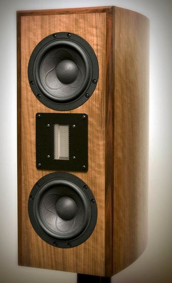
Those look like Scan 15W drivers. Wiring two 8 ohm in parallel would cause you considerable design headaches. Why? Because all the good designs for that driver used single need a presence notch around 1kHz. Paul Carmody did this Troels Gravesen did this.
Problem is the notch takes impedance near 4 ohms even with the 8 ohm driver. Impossible to do with parallel wiring. 😎
Whether it's right or wrong, it's certainly not unworkable as GeoofMillar pointed out!
Tritrix_pg_1
All discussion of the greater efficiency of parallel wiring is just a matter of taste IMO.
Series wiring is actually MORE EFFICIENT electrically. You just turn the volume up. That's because a high impedance load draws less current, so heats up the amplifier less for a given SPL. Power equals V squared / Resistance or Mr. Ohm was wrong. 😀
Here's another good reason to use 4 ohm drivers in series. Consider this fine Scan design by the late Rick Craig of Selah Audio:
Those look like Scan 15W drivers. Wiring two 8 ohm in parallel would cause you considerable design headaches. Why? Because all the good designs for that driver used single need a presence notch around 1kHz. Paul Carmody did this Troels Gravesen did this.
Problem is the notch takes impedance near 4 ohms even with the 8 ohm driver. Impossible to do with parallel wiring. 😎
So what would be better overall, 4 ohms in series or 16 ohms in parallel? I know 16 ohms limits ones choices but just wondering.
I don't think anybody mentioned efficiency (normally given in percent) Steve. Sensitivity, yes, which is a different question.
As I and a few others have already noted above, series-wiring is fine, but if the drivers are sharing the same acoustic volume, then they need to be a tight pair-match or you can run into problems, particularly if it's a vented load, an example of which GM has already given. Lynn Olson gives a brief summary here: https://www.diyaudio.com/forums/multi-way/343771-drivers-ariel-speakers-5.html#post5959759
Regarding 2 x 4ohm in series, or 2 x 16ohm in parallel, all other things being equal, I would go with the latter for that reason. If you can put them in independent volumes, some of the potential issues with series are reduced. However, it's worth keeping in mind that things are not always equal. As I mentioned above, when I designed a couple of MTMs using SB units, I had the option of using their 8ohm drivers (for parallel wiring) or 4ohm (for series wiring). The 8ohm units I measured exhibited significantly wider deviations than the 4ohm coil versions from published spec., so I ended up having to use the series-wired 4ohm units as the 8ohm drivers simply weren't consistent enough.
I'm not quite sure why a nominal 4ohm load is being touted as a major problem in & of itself. Most amplifiers with a half-decent power-supply won't be troubled by a nominal 4ohm load even in the bass, providing it isn't excessively reactive, which is a question of driver choice and enclosure / crossover design rather than an innate issue with the baseline average impedance.
Last edited:
I generally use quantum electrodynamics, QED, as it is known. The most accurate and tested physical theory of electrons.... 😀
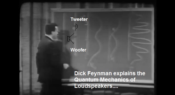
What is going on in an MTM with a single electron Dirac Delta impulse?
Dirac delta function - Wikipedia
Clearly with series wired, it goes through both drivers. With parallel wired it only goes through one or the other. Quantum mechanically, different situations and experiments. 😎
I tried something more mundane just now, since Scott has not presented any evidence whatsoever that parallel in a common enclosure is better than series, albeit with mismatched drivers. My simple notion is that a 50Hz bass and a 60Hz bass will produce a beating 55Hz output if it goes into beating or oscillation.
To quote the all-wise Mr. Lynn Olson is just a smokescreen. The Ariel versions 1 to 3 and the ME2 were both common enclosure parallel wired. Versions 4 to 6 were seperate enclosures or lines. He did favour separate for his parallel wiring, and that makes sense to me.
The Ariel, Part I
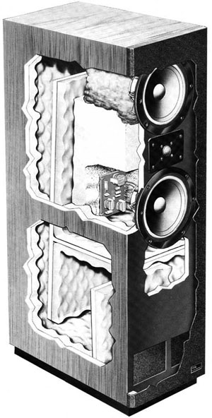
The TDL Studio 3 was 2X 16 ohm in paralllel, common enclosure:
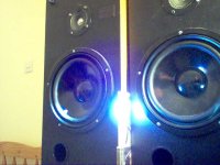
My own experiments were inconclusive. I wasn't sure which way the load driver was moving when I pressed in the other one. I used a torch and a piece of tissue on the bass. But renoticed the effect of shorting a bass unit and tapping it with a tight short,and a crackly one. One of the easy ways to test a bass unit for function.
I need laser beams, stroboscopes and a signal generator for further work.
What is going on in an MTM with a single electron Dirac Delta impulse?
Dirac delta function - Wikipedia
Clearly with series wired, it goes through both drivers. With parallel wired it only goes through one or the other. Quantum mechanically, different situations and experiments. 😎
I tried something more mundane just now, since Scott has not presented any evidence whatsoever that parallel in a common enclosure is better than series, albeit with mismatched drivers. My simple notion is that a 50Hz bass and a 60Hz bass will produce a beating 55Hz output if it goes into beating or oscillation.
To quote the all-wise Mr. Lynn Olson is just a smokescreen. The Ariel versions 1 to 3 and the ME2 were both common enclosure parallel wired. Versions 4 to 6 were seperate enclosures or lines. He did favour separate for his parallel wiring, and that makes sense to me.
The Ariel, Part I
The TDL Studio 3 was 2X 16 ohm in paralllel, common enclosure:
My own experiments were inconclusive. I wasn't sure which way the load driver was moving when I pressed in the other one. I used a torch and a piece of tissue on the bass. But renoticed the effect of shorting a bass unit and tapping it with a tight short,and a crackly one. One of the easy ways to test a bass unit for function.
I need laser beams, stroboscopes and a signal generator for further work.
Attachments
Last edited:
Come now Steve, you're being disengenuous at best. 😉 To introduce some fact rather than tenuous references to theoretical physics:
-All versions of the Ariel have had the drive units wired in parallel. Given the impedance of the P13 and the object of achieving over 90dB sensitivity in the lower regions, this was a necessity.
-The first version of the Ariel was a simple single-fold line with a terminus near the top of the pipe.
-The 2nd and 3rd versions of the Ariel enclosure had the drivers in a Y shaped line where initially independent pipes were merged about half-way down the box, with the object of placing the pipe terminus at the bottom of the enclosure and thereby picking up some boundary gain. While convenient in construction terms, this unfortunately introduced a loading / resonance issue, because the initial stages of the pipe (i.e. for the upper and lower driver) were of physically different lengths. If you are interested, it is technically possible, with the correct geometry & acoustic design, to solve this -they do it all the time in manifold / exhaust design for example. But it's not a straightforward process either.
-From the 4th version of Ariel onwards, Lynn placed the drivers in acoustically separate volumes of equivalent acoustic length, removing the disparity & resonance issues caused by trying to combine dissimilar pipe lengths without being able to engage in extensive measurement or modelling of the detailed resonant behaviour. This had nothing at all to do with the electrical connection of the drive units, and everything to do with correcting issues with the earlier versions of the Ariel enclosure's acoustic design. These are not 'smokescreen' as you claim, but documented facts: the information is available to everyone.
-If you had ever tried wiring mismatched drive units in series, and placed them in a common vented volume, you would quickly see why this can become an issue for the reasons Lynn described, and you for one reason or another forgot to address. I'll quote Lynn's post here, verbatim, as it is of very specific relevance to this point, and means that others don't even need to follow the link I provided above:
GM, Lynn (and I for that matter) have all experienced, and pointed out what can happen when mismatched units sharing the same vented volume, are wired in series: you will find one modulated by the other, with increasing severity as the disparity increases. This is not a problem with a good pair match, but it certainly can be for units that are not. I would politely add that you appear to be trying an inversion by suggesting that I need to 'present evidence' when only a couple of hours earlier you admitted your ruminations were / are actually 'only an untried theory of mine [as in yourself]'. The onus of proving it, by scientific convention, therefore lies upon you, not the other way around.
-All versions of the Ariel have had the drive units wired in parallel. Given the impedance of the P13 and the object of achieving over 90dB sensitivity in the lower regions, this was a necessity.
-The first version of the Ariel was a simple single-fold line with a terminus near the top of the pipe.
-The 2nd and 3rd versions of the Ariel enclosure had the drivers in a Y shaped line where initially independent pipes were merged about half-way down the box, with the object of placing the pipe terminus at the bottom of the enclosure and thereby picking up some boundary gain. While convenient in construction terms, this unfortunately introduced a loading / resonance issue, because the initial stages of the pipe (i.e. for the upper and lower driver) were of physically different lengths. If you are interested, it is technically possible, with the correct geometry & acoustic design, to solve this -they do it all the time in manifold / exhaust design for example. But it's not a straightforward process either.
-From the 4th version of Ariel onwards, Lynn placed the drivers in acoustically separate volumes of equivalent acoustic length, removing the disparity & resonance issues caused by trying to combine dissimilar pipe lengths without being able to engage in extensive measurement or modelling of the detailed resonant behaviour. This had nothing at all to do with the electrical connection of the drive units, and everything to do with correcting issues with the earlier versions of the Ariel enclosure's acoustic design. These are not 'smokescreen
-If you had ever tried wiring mismatched drive units in series, and placed them in a common vented volume, you would quickly see why this can become an issue for the reasons Lynn described, and you for one reason or another forgot to address. I'll quote Lynn's post here, verbatim, as it is of very specific relevance to this point, and means that others don't even need to follow the link I provided above:
Way back when I was at Audionics and dinosaurs swam in the Willamette River, I got curious and T/S measured all our incoming production drivers. I wanted to know where the production variations came from, aside from the obvious duds (which were about 3%).
The three main things to measure are compliance, moving mass, and BL product ... they pretty much set the T/S parameters, assuming the driver is operating in the linear-excursion region. Moving mass, perhaps not surprisingly, is very consistent ... the only thing that varies significantly is a tiny amount due to some drivers having a little more glue then others, but that's only a fraction of gram.
BL is interesting. The "L" is very consistent, since it's nothing more than turns on a voice coil, and that's done with a machine that counts turns. But "B", regrettably, can vary by a dB or two, since it's not possible to charge magnets consistently. The variation in "B", in fact, is responsible for most of the efficiency variations in production drivers, and requires the drivers to be pre-sorted in production so you don't get a mismatch between L/R pairs. It also throws off crossover design, since tweeters vary along with bass drivers ... so the crossover will probably need a tapped resistor, or one selected in production after testing.
The other thing that varies is compliance. This is even worse, since it is mostly controlled by the spider, not the surround, and the spiders are very difficult to make consistently. First, they arrive from the manufacturer much stiffer than they will be after the customer has used them for a while, so they have to be "burned in" for some hours, and even then it takes them a while to settle down. And they up settling down to different values. Not good.
Now, in a closed box, this doesn't much matter, since compliance is mostly determined by box volume, not the stiffness of the spider, so the finished speakers end up measuring pretty similarly. In a vented box, the alignment slides along a continuum, not far from the ideal set of book values, so that's fairly acceptable as well. Some ripples might appear if the compliance is way off (like 30% high), but that's why all new drivers are tested before and after burn-in (and some are rejected and sent back).
This is where wiring drivers in series can really bite you. If the drivers were perfectly matched (hah!), no problem. But in the world where we live in, they are all over the place, especially the compliance factor, which might never settle down to a final value, depending on humidity, abuse, etc. etc. By contrast, the mass is going to stay the same until complete destruction, and BL is only going to change if the magnet gets weaker over time (which doesn't really happen with ceramic magnets).
You can see the obvious problem if they are wired in series, especially if the enclosure has a common volume. The Fs will NOT match, so you get two impedance peaks, not one. This isn't good, since the drivers are now transferring energy between each other, at least in the Fs region. Worse, the Fs of each driver is not a stable value, since compliance shifts with drive level ... it's not even very linear, unless you go to exotic double spiders with one reversed, or the really old-school "spider" assemblies made of copper or whatever.
This is why it's a good idea to step away from idealized models and take a good look at the real-world driver, and not just one, but a whole bunch of them in a production lot. It's important to know where the source of variation is coming from, and what can be done to alleviate it, or at least make the production loudspeaker not as sensitive to it. The design should never depend on idealized drivers.
GM, Lynn (and I for that matter) have all experienced, and pointed out what can happen when mismatched units sharing the same vented volume, are wired in series: you will find one modulated by the other, with increasing severity as the disparity increases. This is not a problem with a good pair match, but it certainly can be for units that are not. I would politely add that you appear to be trying an inversion by suggesting that I need to 'present evidence' when only a couple of hours earlier you admitted your ruminations were / are actually 'only an untried theory of mine [as in yourself]'. The onus of proving it, by scientific convention, therefore lies upon you, not the other way around.
Last edited:
My reference to Quantum electrodynamics was purely a humorous response to Allen's joke about electron flow. In fact I used a bit of electron flow to do a further test. But a bit of good maths does no harm. Just you have to model the right thing.
What I next did was wire up two reflex speakers positive to positive with a speaker cable. Then added a 1.5V battery to the positive input to one of the speakers. To my surprise, the speakers moved in opposite directions! 😕
I could see my mathematical and loudspeakering reputation in tatters here. Ol' system can't even wire up his basses in phase, they say! 😱
But on testing individually I found the speakers behaved correctly. Moving out when connected positive to positive on the battery. Phew. 🙂

It depends where you put the battery what happens, when I drew the diagram.
My notion was to try and figure out if we can get away without individual enclosures.
And I think my series wiring theory (even with mismatched drivers) is as good as anybody's. Might work, might not. Lynn used a valve amp too, which isn't the last word in amplifier damping, so some things might get out of control. Who knows, really?
We need a definitive test. Otherwise it's just more snake-oil, like capacitors. Unfortunately I don't have an MTM to hand.
But Curt Campbell doesn't seem to see any problem with common enclosure here:
Tritrix_pg_3
What I next did was wire up two reflex speakers positive to positive with a speaker cable. Then added a 1.5V battery to the positive input to one of the speakers. To my surprise, the speakers moved in opposite directions! 😕
I could see my mathematical and loudspeakering reputation in tatters here. Ol' system can't even wire up his basses in phase, they say! 😱
But on testing individually I found the speakers behaved correctly. Moving out when connected positive to positive on the battery. Phew. 🙂
It depends where you put the battery what happens, when I drew the diagram.
My notion was to try and figure out if we can get away without individual enclosures.
And I think my series wiring theory (even with mismatched drivers) is as good as anybody's. Might work, might not. Lynn used a valve amp too, which isn't the last word in amplifier damping, so some things might get out of control. Who knows, really?
We need a definitive test. Otherwise it's just more snake-oil, like capacitors. Unfortunately I don't have an MTM to hand.
But Curt Campbell doesn't seem to see any problem with common enclosure here:
Tritrix_pg_3
Last edited:
I can think of a way to test these notions:
Bridge methods might be good, variations for AC of a wheatstone bridge.. You will need to place a few resistors around.
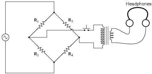
Because a driver has a motional impedance as well as a static one, you ought to be able to pick up a difference in voltage across two series wired speakers, or a difference in current through two parallel wired ones if they are not moving in unison. Ideal for a person with an oscilloscope to try too.
Bridge methods might be good, variations for AC of a wheatstone bridge.. You will need to place a few resistors around.
Because a driver has a motional impedance as well as a static one, you ought to be able to pick up a difference in voltage across two series wired speakers, or a difference in current through two parallel wired ones if they are not moving in unison. Ideal for a person with an oscilloscope to try too.
Sure, there may be a difference. First you measure impedance on each driver separately but you must play both at once when doing each measurement. Then comparing drive level to each driver vs frequency should do it.
Not sure that it needs to be a big deal.
Not sure that it needs to be a big deal.
Lynn used a valve amp too, which isn't the last word in amplifier damping, so some things might get out of control. Who knows, really?
As it happens, Lynn was taking about work he did while at Audionics during the 1970s. The speakers in question were mostly designed for the commercial market of the era, i.e. transistor amps, with much lower output impedances than the majority of single ended valve designs. However, the exact loudspeaker or amplifier model aren't particularly relevant: he was simply explaining, with a little personal background, some of the issues with driver inconsistency and the problems these can cause.
Quite -as I mentioned several times above, it isn't a problem providing the drivers are a good pair-match. You just have to make sure they are. I've used series-wired 4ohm units in several DIY and commercial designs myself.
Last edited:
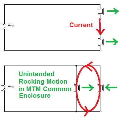
For people who don't know what me and Scott are yakking about, it is the problem of two MTM drivers in a single enclosure:
Will they interact by air pressure?
I have already suggested the only way I can think of to measure this by comparing voltages and currents since motion affects impedance:
This is as frustrating as "The Great Capacitor Debate" which has no convincing measurements I have ever seen.
Simulators can't do this stuff. You do get very different impedances when wiring two different closed boxes in series and parallel, but that doesn't tell you anything about how an MTM behaves.
As it goes, parallel gives you a small single peak, series a smeared double peak. But resonances are often made WORSE by exact matched tuning. So convince me I am wrong, if you have the measuring equipment. It would be a good bit of testing. Better than thought experiments and opinions and quoting other sources.
If their is a mismatch with drivers.
If wired in series the overall sound takes on the weakest driver.
Described as rocking.
I just think of cone rocking from un equal pressure.
Something that would happen in many speaker enclosures with the driver offset.
In live sound with large 18" or 21" drivers in a reflex cabinet.
It is recommended to use 4 ports at each corner
to equalize port pressure and reduce cone rocking.
Cone rocking being more prevalent with larger cone areas
Last edited:
I tried something more mundane just now, since Scott has not presented any evidence whatsoever that parallel in a common enclosure is better than series, albeit with mismatched drivers.
FWIW, my extreme real world example was dual 16 ohm Altec 421A wired in parallel in a large vented horn cab, so in this case if parallel helped, then guessing the cab's large shelf vents may have had more 'control' on the lower driver, leaving the top one in a somewhat leaky sealed 'box'?
Regardless, Thorsten proved such mismatches in a vented alignment can work: 404 Error - Page Not Found

Greg, this link seems to work - http://web.archive.org/web/20120317...ndell/xentar/1179/theory/dddllqd/dddllqd.html
It's an interesting concept; I was always a bit hazy on the idea of dissimilar units sharing the same Vb though. Not for any series or parallel wiring reasons; mathematically it seems to work fine as far as that goes, but to use Thorsten's Lowther & some form of larger partnering unit as an example, it strikes me that if the wick gets cranked, the larger unit is potentially going to start modulating the smaller since there's no isolation, and a short-stroke wideband like may not be too happy under those conditions. Depends on how extreme you take it or the dissimilarities no doubt, but in general, that's why midrange drivers are usually isolated in their own subenclosures, right?
Last edited:
I wouldn't go so far as to say that, the idea of a midrange being left to be pushed by a larger woofer is an extreme example.
No, do we actually know what is happening? You mention modulation. Each woofer should be handling the same signal at the same time, so isn't this something else?
No, do we actually know what is happening? You mention modulation. Each woofer should be handling the same signal at the same time, so isn't this something else?
If their is a mismatch with drivers.
If wired in series the overall sound takes on the weakest driver.
Described as rocking.
I just think of cone rocking from un equal pressure.
Something that would happen in many speaker enclosures with the driver offset.
...snip
"takes on the weakest driver"? Didn't follow that... 😕
http://web.archive.org/web/20120317074638/http://www.fortunecity.com/rivendell/xentar/1179/theory/dddllqd/dddllqd.html
Didn't find that terribly precise either... 😕
Now "Rocking Mode" I do know. Spider needs to be good.
And Common-Mode and Differential-Mode is familiar to Amp people to reject Mains Hum from the Earth over long cables:
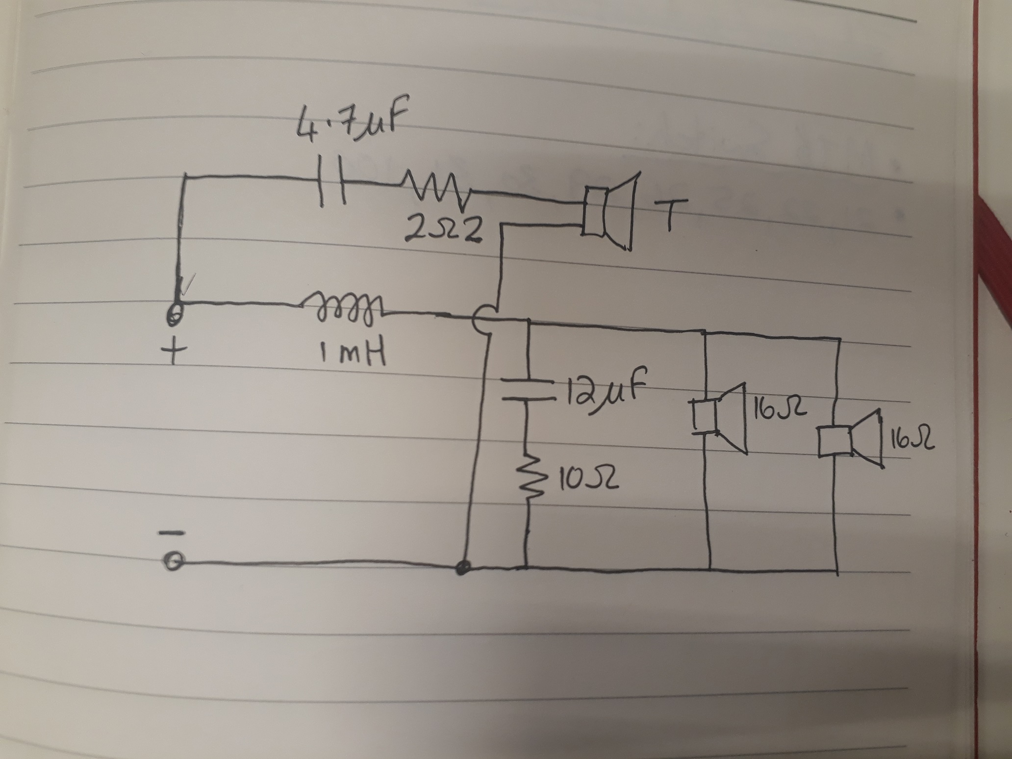
The person who might potentially be in trouble here is our own Joe Rasmussen of Elsinore fame if you guys are right:
Elsinore Mk1
Elsinore Gallery
4 drivers in a common enclosure, series wired. Sort of 2.5 way. 😱
- Home
- Loudspeakers
- Multi-Way
- MTM Speaker drivers