Okay, so it seems that the circuit is working as intended!
What about the 4k7 (bias) resistor? R2 in my schematic. Would it need to be changed?
I got some major oscillation, so decided to swap the primary. It worked!
I went with a resistor as low as 180R! And I got almost no noise, but gain was reduced significantly.
I would like to try and use the 3-4 winding, but unsure how to apply it in my usecase. Perhaps it could lower hum, thus allowing a higher gain to be used.
Using a 100 ohm resistor for the negative feedback loop gave me the following readings (measured when the amp is playing).....
Measuring Pin 3 of EZ81 gives me 270V.
Measuring Pin 3 of ECL86 gives me 240V.
Measuring Pin 7 of ECL86 gives me 6.34V
I thought the overall voltage drop is interesting, but don't know what it could imply.
Measuring Pin 3 of EZ81 gives me 270V.
Measuring Pin 3 of ECL86 gives me 240V.
Measuring Pin 7 of ECL86 gives me 6.34V
I thought the overall voltage drop is interesting, but don't know what it could imply.
But is the gain enough for lets say a cd-player as the source? If so, than why would you want to lower the amount of feedback?
What kind of hum are you experiencing? If it's 50 Hz, than it could be heater induced. Is the filament supply grounded at one side? Or if any, at the centre-tap on the power transformer? Did you twist the wires for the filament supply into eachother?
Addition:
The voltage differences are small. Probably the tube is still setting a bit. I would be surprised if it had anything to do with the feedback. And if you are measuring while the amplifier is playing music, the measurements could be influenced by the AC (signal) 'riding' on de dc-voltage.
I'm surprised by the amount of feedback you can apply though.
Last edited:
Wires are twisted.
Using two 180R 3W resistors to make a virtual ground.
One side is not grounded.
Using two 180R 3W resistors to make a virtual ground.
One side is not grounded.
The gain is plenty! Even when going through the 100R resistor.
Just concerned about the stability. I don't have anything more than a multimeter to test very basic things.
Just concerned about the stability. I don't have anything more than a multimeter to test very basic things.
Also, if I completely skip the 100R resistor, and send a wire straight to the negative feedback loop, I get nothing.
Either I'm messing something up, or this circuit is super ultra mega stable!
Either I'm messing something up, or this circuit is super ultra mega stable!
If you would remove C2 = 50 uF at the cathode of the first stage, you create extra local negative feedback there. That will lower the gain somewhat.
Addition: If you are able to silence the amplifier like that, than it's surely very stable. But I realize that I never tried to go so far myself.
Addition 2: However, it could be possible that things are not right with so much feedback but that it's going on on a frequency that you can't hear.
Addition: If you are able to silence the amplifier like that, than it's surely very stable. But I realize that I never tried to go so far myself.
Addition 2: However, it could be possible that things are not right with so much feedback but that it's going on on a frequency that you can't hear.
Last edited:
Using a 100 ohm resistor for the negative feedback loop gave me the following readings (measured when the amp is playing).....
Measuring Pin 3 of EZ81 gives me 270V.
Measuring Pin 3 of ECL86 gives me 240V.
Measuring Pin 7 of ECL86 gives me 6.34V
I thought the overall voltage drop is interesting, but don't know what it could imply.
There is just the possibility that you have super sonic oscillation (outside your hearing range) that is 'sucking up' the volts.
The R-type circuit has a 1.8kΩ feedback resistor, I would centre on that and work out problems from there.
Okay, so some additional testing was completed.
180R seems to be the best resistance for num/noise/distortion reduction. Voltages are not dropped. And it sounds perfect!
I only have one concern, which is the value 180R itself. I have been told that such a high current going from the OPT to the cathode (pin 2) is not healthy. If anyone here can confirm or deny that theory it'd be great!
I will upload the new schematic in the next post.
I wouldn't know about too much current with the 180 Ohm feedback resistor. I never heard of it before. I thought this type of feedback is all about the amount of voltage that (in this case) gets devoloped over the 100 Ohm resistor in the cathode lead.
But I do still think that in this case 180 Ohm is unusually low.
I repeat my suggestion to skip C2. This will lower the gain of the first stage. You can than higher the value of the feedback resistor a bit to reduce the amount of feedback so as to reach the same total gain of the amplifier again. The advantage of this is that skipping C2 doesn't affect stability, while the larger value of the feedback resistor does improve stability.
Addition: Using the possibility of your OPT to apply cathode feedback to the power stage would lower the gain of the power stage. The value of the cathode resistor of the power stage than has to be lowered to 150 Ohm because the dc-resistance of winding 6-7 is 33.9 Ohm, so the total resistance becomes 183.9 Ohm. Ofcourse than the cathode resistor and capacitor have to be connected to 6 of the OPT instead of ground like it is now. By applying this cathode feedback, you can higher the value of the feedback resistor some more to reach the same total gain of the amplifier.
What are you using as a source (what is the input voltage you are using now)?
Last edited:
My mistake. It is about the voltage, not current.
I have changed values between 'open loop', 900R, 180R, etc... they all measure 1.59V at pin 2 of the ECL86.
But I don't think it's very stable at lower impedances. 100R and it starts to distort.
I may add a 10K pot, with a 180R resistor in series.
For my source I'm using my LG phone.
To be honest, I wish it were stable all the way down. Then I could simply use a pot to adjust the volume. And as the volume increases, so would distortion, making it dead silent at lower volumes.
I will try your suggestions later in the day @PFL200. Sounds interesting. If I skip C2, do I have to wire the feedback loop wire between 4k7 and 100R, or directly to Pin 2 of ECL86?
In order to minimize hum in a SE circuitry like this one it is important *imho* to exactly replicate the power supply schematics of the donor device. That supplementary OT primary winding doesn't serve as a choke here, but as part of a hum cancelling scheme that was typical in European radios of the 1950ies and 1960ies. You also need to use those 3k3 resistors between these extra windings and the following filter cap. The 330R isn't necessary if you do it this way.
Best regards!
Best regards!
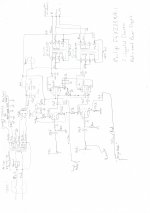
FYI, here is the schematic for the original power supply and audio stage for this radiogram - it is South African-made Philips F4VZ25A/R1. No schematics were available so I had to trace it. I am for my sins restoring it. The audio and AM are fine, struggling with the FM.
Edit: I neglected to show the NFB connected to pins 6 of the OPTs. As Alan4411 suspected, the NFB does go via the tone controls to the cathode of the preamp triode. And Kay correct about the hum cancelling as you can see.
Edit: I neglected to show the NFB connected to pins 6 of the OPTs. As Alan4411 suspected, the NFB does go via the tone controls to the cathode of the preamp triode. And Kay correct about the hum cancelling as you can see.
Attachments
Last edited:
Thanks, Kerron!
Everyone, here is the final revision of the headphone amp (hopefully). I have added a choke, and utilized every bit of the output transformers. This is going to be fun!
On another note, if you use two of these output transformers, it's best to connect them in parallel, as that is how they were originally used.
I will post a build thread when I'm done with these. For now, thanks everyone for helping and contributing!
Attachments
If I understand the workings of anti-hum windings on OPT's good enough, the amount of current flowing through it is important for proper functioning. In a radio the current of the radio part probably is in the order of 40 mA or so. When you would use that anti-hum winding in the amplifier of TS the current through the anti-hum winding would ofcourse be much lower. I would think that because of that, the effect on hum will be minimal.
The OPT in the schematic in post #12 came out of a Philips EL3516 taperecorder. The amount of current running through the anti-hum winding in that tape recorder was almost the same as the amount of current that is now running through it in the amplifier of post #12.
The OPT in the schematic in post #12 came out of a Philips EL3516 taperecorder. The amount of current running through the anti-hum winding in that tape recorder was almost the same as the amount of current that is now running through it in the amplifier of post #12.
Good estimate there! Looking at the valves in the radio section (ECH81,EBF89, and ECC85 for FM), the draw would be about 25mA/40mA AM/FM, plus about 3-4mA for the ECL86 triodes, but it would be evenly split between the 2 OPTs.
Now it will only be the triodes, so the hum reduction will certainly be reduced. Zilch could increase that by running the two "chokes" in series, which is possible since they can be connected separately. He could also maybe experiment with just putting a say 10mA load on that section of the supply to see if the additional current reduces noise?
Now it will only be the triodes, so the hum reduction will certainly be reduced. Zilch could increase that by running the two "chokes" in series, which is possible since they can be connected separately. He could also maybe experiment with just putting a say 10mA load on that section of the supply to see if the additional current reduces noise?
That hum compensation doesn't rely on the current ratio at all. Instead, the winding ratio of primary and comp must equal the ratio of the tube's internal plate resistance and the filter resistor value.
Best regards!
Best regards!
- Home
- Amplifiers
- Tubes / Valves
- Need help with ECL86 tube amplifier