Am new to electronics and playing with them.
Which I suppose means I should anticipate "burned by the stove" type lessons lol
Well I was "burned by the stove" today and learned an important, however fundamental lesson today lol
Verify circuits prior to powering dut.
Just made a simple resistor bank to dump amp power into.
first iteration and testing went well. used an older amp and all went nearly as expected. issue being one of the resistors was getting hotter than the others.
The resistors are 8oh 100w and I thought I had them wired as 2s2p. However only by happenstance I had wired and connected them such that it actually only 8ohm 100w, the other three resistors in the bank were bypassed because of how I connected.
So anyways I redo the resistor circuit and am super confident is correct.

I connect the speaker wire to the resistor bank(s) and amp outputs, toss on the input signal and turn up the power.....cue -20db or so and clicky pop poof and some smoke.
DOH!!!
This AVR was from my second ht setup. not intended to be the dut to practice / play with without care if it breaks.
So first examined it.
Thankfully, no visible damage. the power output transistors of JUST the left channel are both three way shorted. and one side of the dual emitter resistor is open.
I audited a few smaller components I believe are in the path and those checked out fine.
I ordered up the power transistors / dual resistor i'll find in some other amp am sure.
So onto what went terribly wrong.
To help my simple brain I put the circuit into a diagram. I knew which resistor bank was used for the left channel, the one confirmed that blew, right channel is fine. Immediately I thought I must have somehow* connected the left channel as a short.
such as imaged below. Absolutely plausible given the "mess" the resistor bank is.

*But I absolutely recalled checking the ohms specifically as the amp would see, that is including the speaker wire; and BOTH channels were exact same 8.3 ohms (Bank is 8.0-8.1)
So, checked out how it was actually wired, and it was same as imaged next below.

Only other thing I can think of is a strand of wire possible fell into the amp and some how shorted out just the left channel power transistors and emitter resistor.
So think it's most likely how I had the left channel connected to the resistor bank that caused it to fail.
The right channel was connected symmetrically, and it didn't blow out.
So is the resistor bank the left channel was connected to not correct? is it because of the yellow highlighted connection?
Also I suppose, since not experienced with resistor failure and especially of these values, perhaps they can measure fine with dmm but under load different story. Is that possible?
So far, while less dynamic an experience, I think 200$ in electronics education would have been better value here lol (here's hoping it will be fixed with the replacement power transistors and emitter resistor lol)
(I have quite an imagination; I envision a possibility is independent resistors not having same value. in that...
firstly, electricity likes to flow the path of least resistance.
the circuit, as the left channel is connected, depends on each paralleled sub-circuit's resistors be of nearly exact resistance. AND that that difference in resistance is more crucial the higher the power.
so in this case, perhaps the wiring of the left channel's resistor bank's sub-circuit with the yellow highlight is exacerbating any difference in resistance value.
And with that, the resistance was all wonky dependent on the power put through it....hmmmm I wonder lol
Which I suppose means I should anticipate "burned by the stove" type lessons lol
Well I was "burned by the stove" today and learned an important, however fundamental lesson today lol
Verify circuits prior to powering dut.
Just made a simple resistor bank to dump amp power into.
first iteration and testing went well. used an older amp and all went nearly as expected. issue being one of the resistors was getting hotter than the others.
The resistors are 8oh 100w and I thought I had them wired as 2s2p. However only by happenstance I had wired and connected them such that it actually only 8ohm 100w, the other three resistors in the bank were bypassed because of how I connected.
So anyways I redo the resistor circuit and am super confident is correct.
I connect the speaker wire to the resistor bank(s) and amp outputs, toss on the input signal and turn up the power.....cue -20db or so and clicky pop poof and some smoke.
DOH!!!
This AVR was from my second ht setup. not intended to be the dut to practice / play with without care if it breaks.
So first examined it.
Thankfully, no visible damage. the power output transistors of JUST the left channel are both three way shorted. and one side of the dual emitter resistor is open.
I audited a few smaller components I believe are in the path and those checked out fine.
I ordered up the power transistors / dual resistor i'll find in some other amp am sure.
So onto what went terribly wrong.
To help my simple brain I put the circuit into a diagram. I knew which resistor bank was used for the left channel, the one confirmed that blew, right channel is fine. Immediately I thought I must have somehow* connected the left channel as a short.
such as imaged below. Absolutely plausible given the "mess" the resistor bank is.
*But I absolutely recalled checking the ohms specifically as the amp would see, that is including the speaker wire; and BOTH channels were exact same 8.3 ohms (Bank is 8.0-8.1)
So, checked out how it was actually wired, and it was same as imaged next below.
Only other thing I can think of is a strand of wire possible fell into the amp and some how shorted out just the left channel power transistors and emitter resistor.
So think it's most likely how I had the left channel connected to the resistor bank that caused it to fail.
The right channel was connected symmetrically, and it didn't blow out.
So is the resistor bank the left channel was connected to not correct? is it because of the yellow highlighted connection?
Also I suppose, since not experienced with resistor failure and especially of these values, perhaps they can measure fine with dmm but under load different story. Is that possible?
So far, while less dynamic an experience, I think 200$ in electronics education would have been better value here lol (here's hoping it will be fixed with the replacement power transistors and emitter resistor lol)
(I have quite an imagination; I envision a possibility is independent resistors not having same value. in that...
firstly, electricity likes to flow the path of least resistance.
the circuit, as the left channel is connected, depends on each paralleled sub-circuit's resistors be of nearly exact resistance. AND that that difference in resistance is more crucial the higher the power.
so in this case, perhaps the wiring of the left channel's resistor bank's sub-circuit with the yellow highlight is exacerbating any difference in resistance value.
And with that, the resistance was all wonky dependent on the power put through it....hmmmm I wonder lol
Last edited:
First - attached all images directly to the forum server, because they are not showing up currently.
Hopefully the pictures might help you answer Jacques question, which is the same one i had? Are you trying to get assistance with the repair? Or are you looking for theories on what you did to blow it up?
Lots of variables you have not given, or been clear with, which limits the help we can offer.
Hopefully the pictures might help you answer Jacques question, which is the same one i had? Are you trying to get assistance with the repair? Or are you looking for theories on what you did to blow it up?
Lots of variables you have not given, or been clear with, which limits the help we can offer.
After the receiver is repaired, there are many free on-line electronics lessons that won't blow up the stereo.
Electronics Class - Instructables
https://www.electronics-tutorials.ws/
Online Electronics Classes | Start Learning for Free | Skillshare
Electronics Class - Instructables
https://www.electronics-tutorials.ws/
Online Electronics Classes | Start Learning for Free | Skillshare
Last edited:
What are you trying to achieve?
?
Without additional context is kind of a big question.
I suppose, understand resistors well enough to build a circuit of them with known / specific values; is as reduced "achievement" as I can figure.
After the receiver is repaired, there are many free on-line electronics lessons that won't blow up the stereo.
Electronics Class - Instructables
https://www.electronics-tutorials.ws/
Online Electronics Classes | Start Learning for Free | Skillshare
From my perspective this seems too broad an approach. I've looked for intro into electronics from audio perspective; but no luck.
Exception is "learn by building electronics" I have the book, but not the kits yet. Their pricey....not 200$ avr blown up pricey though lol
That said thank you so much for the links!
First - attached all images directly to the forum server, because they are not showing up currently.
Hopefully the pictures might help you answer Jacques question, which is the same one i had? Are you trying to get assistance with the repair? Or are you looking for theories on what you did to blow it up?
Lots of variables you have not given, or been clear with, which limits the help we can offer.
I tried a different image host; maybe they are showing now? (I see them) Am not sure how to have them hosted on this forum?
Am looking for ideas on why it blew up; specifically the difference between left channel Resistor bank / circuit and the right channel Resistor bank / circuit.
Though without the images....am not asking anything lol
The repair I REALLY hope is just what I found to be spoiled; power transistors / emitter resistor. The display was acting funny, but suspect that is part of it's protection doing what ever (and hoping not spoiled power supply somewhere now; just cannot see how bad display would correlate with blowing a channel so think display is fine)
From my perspective this seems too broad an approach. I've looked for intro into electronics from audio perspective; but no luck.
One must learn the basics before going on to more advanced levels. An undergrad EE will take at least two years of basic courses.
Audio is only an application of electronics and acoustical theory, not a primary area.
Agreed to all of above, but now you want to fix the unit, or you want to tell us all that this can be done as a means of testing units?
But I think we knew that already...
But I think we knew that already...
One must learn the basics before going on to more advanced levels.
Sorry I disagree; and debate is silly.
Last edited:
Agreed to all of above, but now you want to fix the unit, or you want to tell us all that this can be done as a means of testing units?
But I think we knew that already...
It's the circuit I made and if it caused the left channel to blow.
Your diagrams are confusing, because they don't appear to follow standard practice. Both terminals were labeled "power" and you haven't identified a common return path. You should identify the negative terminal.
Were you trying to bridge the amplifier outputs, or what exactly were you trying to do?
If you want to get started in electronics I'd suggest learning Ohm's Law first, then read data sheets to determine the safe operating limits and practices. Determine what area you are interested in within audio, if that's what you like. If it's audio amplification, read about single-ended class A amplification first that uses one or two devices only, then move to opamps, then complex discrete designs. Audio design is a small and simpler piece of the larger pie that is electrical and electronics engineering.
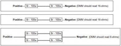
The way you are showing your load resistor bank, looks like you either had a dead short (bad news) or a 2-ohm load (again, bad news).
Look at the diagram below - roughly done, but you should test each bank with DMM and exactly the place you connect the speakers BEFORE making any connections and testing the amplifier. DMM will tell you exactly what you need to know, with an Ohm reading at the positive/negative markings.
If at any time your DMM is not telling you what it should, stop and reevaluate the situation. NEVER connect to a powered amplifier, unless you are confident you have it correct.
Side note - you are making this overly difficult, because that amplifier only puts out about 50W at 8-ohms, so a single resistor would be fine for testing, just not maximum power up to clipping type testing.
Attachments
Even if your array of load resistors was wired and connected correctly (which is indeterminate because your schematic is incomplete) there are some dangerous assumptions in your scheme.
Firstly you should not assume the (-) terminal of one channel can be connected to the (-) terminal of the other channel. Depending on the circuit inside the DUT this may cause instability and instant failure.
Secondly consumer audio amplifiers are normlly not designed to be used at their claimed rated output power. Testing a consumer amplifier's maximum power must be done under the conditions specified in the service manual for the DUT to avoid blowing it up.
An understanding of circuit theory, voltage and current flow is mandatory, not optional, if you want to discuss what you are attempting with others. This is not a matter of opinion or personal choice. Without it you are playing with a jigsaw puzzle without the picture printed on the pieces, and no one else can even see those pieces!
Maybe I'll reiterate.
I made TWO resistor banks. wired as imaged below

Both circuits measured as 8.1ohms and 8.3 including speaker wire to connect to the amp.
The left channel of the amp blew the power transistors and emitter resistor at around -20db, a 500hz sine tone.
Am wondering if it was the circuit that caused the channel to blow out the power transistors.
I made TWO resistor banks. wired as imaged below
Both circuits measured as 8.1ohms and 8.3 including speaker wire to connect to the amp.
The left channel of the amp blew the power transistors and emitter resistor at around -20db, a 500hz sine tone.
Am wondering if it was the circuit that caused the channel to blow out the power transistors.
The way you are showing your load resistor bank, looks like you either had a dead short (bad news) or a 2-ohm load (again, bad news).
Look at the diagram below - roughly done, but you should test each bank with DMM and exactly the place you connect the speakers BEFORE making any connections and testing the amplifier. DMM will tell you exactly what you need to know, with an Ohm reading at the positive/negative markings.
If at any time your DMM is not telling you what it should, stop and reevaluate the situation. NEVER connect to a powered amplifier, unless you are confident you have it correct.
Side note - you are making this overly difficult, because that amplifier only puts out about 50W at 8-ohms, so a single resistor would be fine for testing, just not maximum power up to clipping type testing.
I thought I may have as well, as mentioned, but was not dead short. was wired as we see above.
Of course I did measure, and even lightly tested prior. all checked out.
Was more than confident was correct, and really is point of this post. Am stumped if the two circuits above are different; cause from my understanding they're exactly the same....but my testing blew the left channel. And am presuming it was the slight difference in how they were connected.
Connecting the left channel connection like you drew it here I "blew up" an Onkyo TX-NR709's amp playing with it second diagram is a dead short circuit on the amplifier speaker terminals, which likely would have caused the amplifier to oscillate and fry.
Last edited:
One must learn the basics before going on to more advanced levels. An undergrad EE will take at least two years of basic courses.
Audio is only an application of electronics and acoustical theory, not a primary area.
Sorry I disagree; and debate is silly.
And this is why you've damaged your amplifier.
A basic understanding would tell you WHY you damaged your amp.
Hint; your resistors are not the problem.
Your lack of basic understanding is the reason.
I can see exactly why your amp blew.
But I know you won't accept the answer.
Apparently you know better so have at it.
I thought I may have as well, as mentioned, but was not dead short. was wired as we see above.
Of course I did measure, and even lightly tested prior. all checked out.
Was more than confident was correct, and really is point of this post. Am stumped if the two circuits above are different; cause from my understanding they're exactly the same....but my testing blew the left channel. And am presuming it was the slight difference in how they were connected.
IMO the biggest problem was your first post that was confusing. I don't think you need to go to engineering school to mess around with your stereo. If that was so, this site would have no reason to exist. 😉
I am still not clear what was the point of the exercise. If the goal was to blow up your stereo
 !
!Based on your diagram you just connected 8ohm loads to your amp outputs, that should not have caused magic smoke per se.
I know nothing about the amp and how old it is and the conditions of the caps. It is possible that other issues caused the demise.
Stay positive, dig out the schematic for the amp and figure out how to fix it if you are so inclined. I am sure many people here would be willing to help out.
I made TWO resistor banks. wired as imaged below
The two diagrams in this post are equivalent... for most purposes, electric current doesn't care about going around corners.
I wouldn't suggest hooking up sketchy rigs to amplifiers you wish to preserve, but I guess you've learned that lesson already now?
- Home
- Amplifiers
- Solid State
- I "blew up" an Onkyo TX-NR709's amp playing with it