I recently purchased 2 tda7293 boards and was wanting to build 2 mono block amplifiers with them. I also got two dual power rectifier boards also. Each one is 25v with four 3300uf caps on them with a dual input voltage at 9-17v.new to the amp building thing and been looking at the threads related to my question but haven’t found any solid info to help so my question is how should I go about and what would be the most simple way of powering each one. A 120v transformer mabye? The speakers I have run on either 4-8ohm loads and at 75watts per speaker. I’m also not interested in maximum volume or power. Just wanna be able power them decently with hopes of a good sound with good volume if all goes well. I was thinking maybe making an external power supply or would it be better to put the power supply with amp also in a chassis? Any help in leading me the way would be so appreciated 
I have similar TDA7293 boards. My capacitors are rated at 50V. If yours are rated at only 25Vdc, your transformer should be 15Vac-0-15Vac on the secondary. That will leave you around 20W in 8 Ohm and 40W in 4 Ohm. A higher secondary transformer voltage (18Vac) will mean that the rating of 25Vdc may be slightly exceeded.
From what I could see on amazon these boards (tda7293) connect directly to a transformer. The bridge rectifier boards are used for amps that require DC voltage power input these amp boards require an AC voltage input. In use the bridge rectifier boards would connect directly to a transformer and provide DC to an amp board.
This amp board contains a bridge rectifier so the bridge rectifier boards are not needed.
What you need is a transformer with an output of 12-0-12v to about 25-0-25v and a VA rating above 200.
If you have never worked with AC main power before Please be careful as the chance for injury is very serious.
What kind of transformer? I keep seeing toroidal ones alot but can another type be used? I see step up and step down ones also. This is all very new and the numbers, volts, equations and formulas all confuse me. I blame a lack of patience and overthinking. Power I’m not really worried about. It’s not getting right is my concern. Thank you for the help and any diagrams or help on wiring it al together would be of great help also. Thank you lots
Yes it can be overwhelming when you are faced with so many options or possibilities. One of the first chip amps I built was the Velleman k4003
Look on page 8 of the instructions for a basic diagram of the possible choices for a transformer and what the different wires connect to. I have a similar board with a power supply on it and I will post and image of it connected to a toroidal transformer tomorrow.
Look on page 8 of the instructions for a basic diagram of the possible choices for a transformer and what the different wires connect to. I have a similar board with a power supply on it and I will post and image of it connected to a toroidal transformer tomorrow.
at least a 3amp 15-0-15 if you want to approach making 100 watts
more like a 5-6 amp transformer and those are quite a bit more expensive.
Torroidal not necessary but they are nice - i'm still just getting to building PSU with torroidal transformers. You can offen find them with 200watt rated output for a stereo version of what you made but those are typically running a 28-0-28 and a 12-0-12.
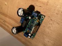
Yes it does look like it has a rectifier and 2 filter caps on the backside of the image - surely the PCB has some kind of +AC grnd -AC labelling. THe trick of AC is that there is no +/- of course because its a wave going +/- but a center tap type transformer is needed here for sure. Then 0v is probably very close to ground 0v which is always helpful.
I'm going to assume you have a pre-amp, if not at least put a 50 to 100k pot on a little board so you can start with it turned down when you test an input audio source.
more like a 5-6 amp transformer and those are quite a bit more expensive.
Torroidal not necessary but they are nice - i'm still just getting to building PSU with torroidal transformers. You can offen find them with 200watt rated output for a stereo version of what you made but those are typically running a 28-0-28 and a 12-0-12.
Yes it does look like it has a rectifier and 2 filter caps on the backside of the image - surely the PCB has some kind of +AC grnd -AC labelling. THe trick of AC is that there is no +/- of course because its a wave going +/- but a center tap type transformer is needed here for sure. Then 0v is probably very close to ground 0v which is always helpful.
I'm going to assume you have a pre-amp, if not at least put a 50 to 100k pot on a little board so you can start with it turned down when you test an input audio source.
On the ac inputs it just say ac-0-ac with no + or -. Im guessing just read it as positive- 0- negative with the letters not upside down? Seems common sense but i would like to be sure. The caps at 50v 2200uf. I have been obtaining parts for this build. RCA inputs, binding posts, toggle switch’s. Got two 50k pots. I read you wanted to have 1/2 or less I believe than than your total so I figured 50k was right looking at the schematics and already have a pre amp. Thanks for the help. Means a lot. Any other help would be much appreciated also. Regards
Lacking a schematic PLEASE post a direct link to the boards you bought. Are you aware you need a heatsink for that chip amp? What chassis and cabinet will you use? Where will you mount connectors , switches , mains cable? Thanks.
Yes I’m aware of a heat sink among other pieces to put the puzzle together and have been reading the boards here and slowly obtaining them. For the chassis I would like to go about building my own. I have a 12”x12” aluminum sheets(0.032in)and steel perforated sheets so I would want to make em myself. Any thoughts if I should do an external power supply or put the amp and supply in the same chassis. I’m been looking through the boards on here getting a better understanding of what to get, build and what not to. The power supply is my main concern cos I’d rather not blow myself up. The boards I got on Amazon and the company is DEVMO https://www.amazon.com/DEVMO-TDA7293-Digital-Amplifier-12V-50V/dp/B07S5HDL8G if that is any help. Thanks
Hey Scott. I ordered some of those boards and was listening to one of them last night. Maybe some of your questions can be answered. First is the power input to the board. AC lacks +/- so the connection pattern is secondary wire -ground wire- secondary wire.
The type of power transformer you pick will provide either three wires (center tapped) or four wires (torid) so when you get that part we can help with the wiring.
You will need a way of insulating the chip from the heat sink electrically as the power inputs show continuity to the chip mounting tab. I used an insulating pad and a shoulder washer. I had difficulty getting small wires to stay in the input connector and bigger wires to fit in the speaker connector but other than that it was simple to wire up. Before connecting a speaker to the board I powered it up and checked the DC voltage at the speaker output with the input shorted. Make sure you check that before using the board with a speaker.
Lastly you will have to put the power transformer in the cabinet with the board. The power supply circuit is on the board with the audio circuit so in my opinion separating the transformer does not make sense. Hope that all helps.
It was foolish of me to say +AC and -AC - and then explain ac has no +/- because its ... AC.+AC grnd -AC labelling. THe trick of .
So if it says AC then yes, either way round both of the 2 ac low voltage outputs from the transformer and the center tap to ground.
If you haven't hooked up a transformer before then yes, be very careful - you have to mount it safely not just put on the table like people in youtube videos. Then have some screw terminals from AC to the transformers high voltage side (which should be labelled and match your local AC) and then you can use clips to hook your multimeter and measure that the low voltage (secondary winding) is giving AC in the zone of what you expect. A 15v tends to give more like 18v AC and even more after it's filter capped to near the peak voltage.
You really need to plan out where and how you mount the transformer and AC power leads - build something for testing (any kind of plastic box reinforced to support the transformer). If you have ground you definitely want to bolt it to the chassis of the transformer. Where I am there are often power sockets with no earth so I build very insulated cases and have plastic covers for my Mains terminals or plastic terminal blocks designed for mains. Those should be secured so they don't just float around - its a real murphy's law situation. If you start dodgy with AC it will lead into more and more dodgy situations until something goes wrong.
So now its clear your board wants a dual rail AC like 15-0-15 AC (which is higher becuase after rectifiers and filters, regulators ... it needs a bit of extra voltage to deliver the resulting voltage. You can use higher voltages of course - with this kind of chip but you'll want to know the capacitors are rated for it.
Last edited:
I’m looking at purchasing two toroidal transformers rated 110v 30va 15-0-15v, 18v-0-18v or 24v-0-24v. My speakers run either 4 or 8ohm at 75 watts each. Would the 18v be a good middle or the 24v?
It was foolish of me to say +AC and -AC - and then explain ac has no +/- because its ... AC.
So if it says AC then yes, either way round both of the 2 ac low voltage outputs from the transformer and the center tap to ground.
If you haven't hooked up a transformer before then yes, be very careful - you have to mount it safely not just put on the table like people in youtube videos. Then have some screw terminals from AC to the transformers high voltage side (which should be labelled and match your local AC) and then you can use clips to hook your multimeter and measure that the low voltage (secondary winding) is giving AC in the zone of what you expect. A 15v tends to give more like 18v AC and even more after it's filter capped to near the peak voltage.
You really need to plan out where and how you mount the transformer and AC power leads - build something for testing (any kind of plastic box reinforced to support the transformer). If you have ground you definitely want to bolt it to the chassis of the transformer. Where I am there are often power sockets with no earth so I build very insulated cases and have plastic covers for my Mains terminals or plastic terminal blocks designed for mains. Those should be secured so they don't just float around - its a real murphy's law situation. If you start dodgy with AC it will lead into more and more dodgy situations until something goes wrong.
So now its clear your board wants a dual rail AC like 15-0-15 AC (which is higher becuase after rectifiers and filters, regulators ... it needs a bit of extra voltage to deliver the resulting voltage. You can use higher voltages of course - with this kind of chip but you'll want to know the capacitors are rated for it.
I’m looking at purchasing two toroidal transformers rated 110v 30va 15-0-15v, 18v-0-18v or 24v-0-24v. My caps at at 2200uf at 50v on the boards and my speakers run either a 4-8ohm load at 75w each. I’m thinking the 18v or 24v would be best suited???
I’m looking at purchasing two toroidal transformers rated 110v 30va 15-0-15v, 18v-0-18v or 24v-0-24v. My caps at at 2200uf at 50v on the boards and my speakers run either a 4-8ohm load at 75w each. I’m thinking the 18v or 24v would be best suited???
1 or 2 by 200w torroidals
Its a 100w amp and a linear power supply is typically in the 60% efficiency range. So, assuming you are going to have 2 for stereo ... you want to actually be able to supply it and think of the future.
Transformers get very hot so its important to have capacity or they are going to run too hot or even fail. My first DIY amps were only like 5-8 watt total for 3 channels total and i needed a 30w transformer to make that stable.
You also need very large heatsinks - much larger than the chip and board.
I’m going to be building two single mono amplifiers or mono blocks. Not the dual mono that I see people building a lot so I’m going to be needing to transformers for them I fugure cos I don’t I’ll be doing and external power supply. I saw two toroidal transformers at 100va with either 12/15/18/22/24v for $30 each today w shipping. Is $30 a good price or can they be found for less?
Price seems ok for 100va - they can be found for less but usually not exactly the way you want customized. I'm still testing some of the asian larger ones so I can't say how good they are. I think this is a fair price for a well made torroid of that size.
It may be undersized per my previous advice so i recommend keeping the voltage to a lower/middling voltage for what that amp can work with.
For example I have a dual LM3886 running on +/- 16v variable PSU which is only about 80va and that sounds fine and doesn't seem to droop or fail because it's not going to operate over capacity. It doesn't get worked very hard its just running the TV sound out of a DAC from the cable tv box optical. It has no other preamp or eq. The speakers are 150w 6 ohm sony 2 way. Everyone I know always says later ... wish I used a stronger power supply, and better design ...
Also depends what impedence your speakers run at ... if you have 4 ohm or less then you want bigger power supply to match the power that can be generated. Remember that voltage droop from underpowered (and overheating) will lead to clipping and bad things.
- Home
- Amplifiers
- Power Supplies
- Power supply for tda7293 mono amp build