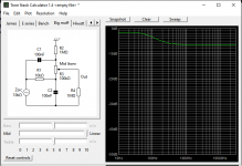
Hi, I am trying to make a bass boost, based on the Big Muff tone stack.
It is smth like a Tilt control - boost low/ attenuate highs, flat, boost high/ attenuate low, around a corner frequency.
I want to use the bass boost setting, smth like low shelving filter.
But, all I can do is smth like high shelving.
The potentiometer in both end positions acts like a high boost, not like tilt.
I cannot make it boost the lows and attenuate the highs (exactly the opposite).
Is it possible to make it work in this transistor configuration?
- common collector (if not wrong)
- frequency dependent gain, via the tone stack in the emitter chain.
I did not want to use the tone stack in passive mode:
- buffer > tone stack > recovery gain stage.
The best would be one transistor (extremely low consumption, battery powered), gain 0 for the highs, gain ~6 db for the low shelf.
Regards, Emil.
Attachments
Last edited:
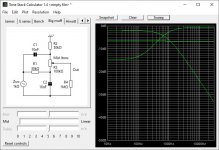
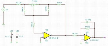
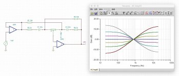
An idea: Active Baxandall tone stack with the bass path only (remove treble path).
Pease find schematic and simulation result. Adpat values to have a fc lower if necessary.
More, please find some minor modifications of Big Muff Tone Control values to have a flat response à 50% and at least 10dB of cut-Boost for bass & treblle with one knob.
Pease find schematic and simulation result. Adpat values to have a fc lower if necessary.
More, please find some minor modifications of Big Muff Tone Control values to have a flat response à 50% and at least 10dB of cut-Boost for bass & treblle with one knob.
Attachments
Good, but what about putting the correction network in a feedback, or in the emmiter chain?
So that there is 0 db gain for the highs.
Otherwise I have to first attenuate it in a passive network, and then amplify to recover amplitude - I guess, there would be more noise.
And there is an EQ after the shelving boost - it adds noise when highs are to the max.
The shelving bass boost is a coorection of the source signal - the EQ cannot handle it. I keep the bass to the max, other settings are almost useless.
Cannot modify the EQ either.
Hi, I maybe don't understand your precise requirements. An additional remark about my scm: replace the pot by the value you want (2 résistors instead of one pot) and you will have a fixed bass correction (cut or boost).
Good luck.
Good luck.
Sounds like the Tilt control on my Quad 34 preamp. You find a pretty good artickle about it here (including scematics):Hi, I am trying to make a bass boost, based on the Big Muff tone stack.
It is smth like a Tilt control - boost low/ attenuate highs, flat, boost high/ attenuate low, around a corner frequency.
Tilt Control
And you will find another description of the circuit here (including component values):
A Paul Kemble web page - equalisation.
You have to look a bit down on that page, search for: "Quad 34"
Great ! The Quad Tilt control might do it.
But, seems it is not working properly on simulation.
I want to do it with two transistors (min. consumption), 9v unipolar supply (battery).
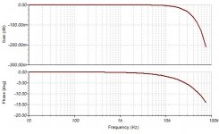
It does not tilt anything. Moving the pot in either directions results in different gain and the same frequency response
But, seems it is not working properly on simulation.
I want to do it with two transistors (min. consumption), 9v unipolar supply (battery).
It does not tilt anything. Moving the pot in either directions results in different gain and the same frequency response
Attachments
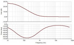
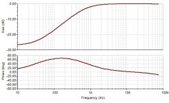
Strange, this is what I get in TINA-Ti using the simple John Bingham 'tilt' control.But, seems it is not working properly on simulation.
Attachments
Last edited:
yes AOP and a resistor divider to have a virtual groud at 4.5V could be a solution for consumption issue. I think best AOP for this task would be OPA1692. this is the AOP with the less power consumption as possible (for specialized audio AOP).
Last edited:
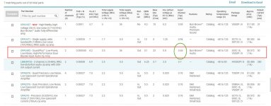
LM324 will work very fine too. The choice of AOP is not so critical as we think. In Marshall, Mesa Boogie effect pedals they use a vintage TLO72 AOP and not a modern Burr-Brown AOP and it sounds good 😉
However, if you have the choice and the budget, you can choose a modern audio AOP.
However, if you have the choice and the budget, you can choose a modern audio AOP.
So not possible to do it with two transistors?
Cannot put the tilt network in Q2 feedback?
(I guess mine is wrong)
----
Cannot find fancy opamps here. Orders, waiting, shipping several times the item cost for some stupid chip.
And probably smd packages only? (NO WAY).
Distortion is not an issue. TL072 would be fine, just the consumption might be better.
----
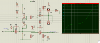
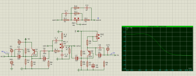
Another attempt - two transistors and the "big muff" tone stack.
The input network (Q1 base bias) is very odd... 1M/ 100k.
I guess it would clip the signal.
p.s. this is for bass guitar onboard preamp - mby it is in the wrong forum section.
Cannot put the tilt network in Q2 feedback?
(I guess mine is wrong)
----
Cannot find fancy opamps here. Orders, waiting, shipping several times the item cost for some stupid chip.
And probably smd packages only? (NO WAY).
Distortion is not an issue. TL072 would be fine, just the consumption might be better.
----
Another attempt - two transistors and the "big muff" tone stack.
The input network (Q1 base bias) is very odd... 1M/ 100k.
I guess it would clip the signal.
p.s. this is for bass guitar onboard preamp - mby it is in the wrong forum section.
Attachments
Last edited:
I think it is possible to do that with transistors but I don't know how. Yes, you could try in the amp section or instrument amp section.
So not possible to do it with two transistors?
Cannot put the tilt network in Q2 feedback?
(I guess mine is wrong)
----
Cannot find fancy opamps here. Orders, waiting, shipping several times the item cost for some stupid chip.
And probably smd packages only? (NO WAY).
Distortion is not an issue. TL072 would be fine, just the consumption might be better.
----
Another attempt - two transistors and the "big muff" tone stack.
The input network (Q1 base bias) is very odd... 1M/ 100k.
I guess it would clip the signal.
p.s. this is for bass guitar onboard preamp - mby it is in the wrong forum section.
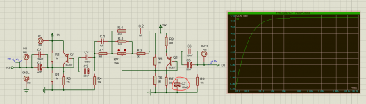
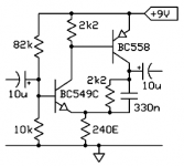
A solution maybe is to not using the feedback path and use the passive circuit between 2 transistors. The first one before the passive circuit wired as commun collector (Collector at V+ and out at emitter for low impedance output to drive the passive circuit) and a second after the passive circuit to had the gain lost by the passive circuit (big muff has an insertion loss of about -6dB I think). It should work 😉
Last edited:
I test with tsc: gain of bass is between -3dB & -17dB. Trebble ia about 0dB and -20-30dB. The middle for bass is about -10dB. So a gain of 10dB for overall gain of the active stage will give you a range of gain for passive circuit (i.e without inserted in the feedback loop) of +/-7 dB for bass and +10dB/-20dB for trebble.
It@Ketje - this is great and compact and I will check it in simulator.
Not quite sure how it works and what is the freq. response.
But...
Can I rise the base resistor from 10k to 100k (and the 82k resistor I guess).
There is a Jfet buffer just before the bass boost.
With a ..33k source resistor, for minimal consumption.
So, the output Z is low.
It works well with instrumental onboard eq and amplifier.
Attachments
Last edited:
The 2 input resistors is for bias voltage. Most of time it is Vcc/2 (as your picture with 2 1Mohms resistors) to have the most voltage range as possible before clipping (Class A). So you could increase the base resistor to 82k without increase the 82k resistor 😉 --> with an output impedance of previous stage of 33k you will have some signal "lost" because of the voltage divider, so you could increase a little bit the resistors again... but best circuit is maybe the most simple. You picture with a simple "class A" jfet buffer is just enough (instead of scm with 2 NPN a PNP transistors). First scm has gain, second is just a buffer with a gain of ~1 and a low output impedance.
Last edited:
- Home
- Source & Line
- Analog Line Level
- shelving bass boost circuit