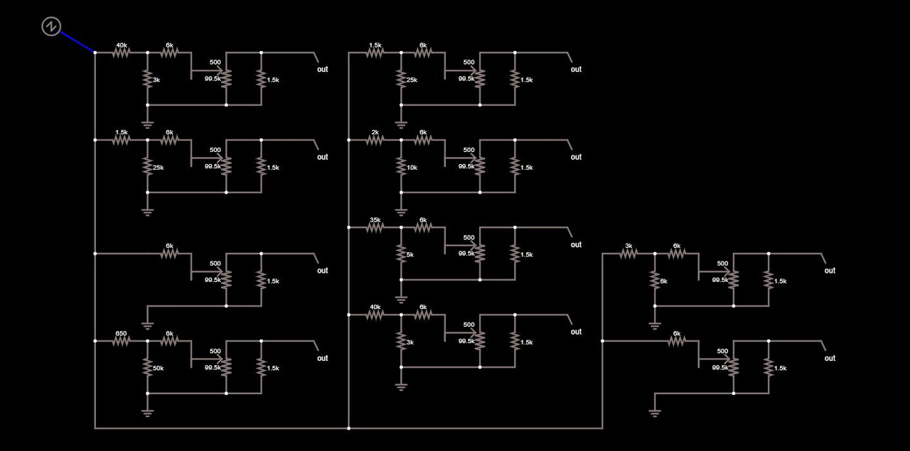
I have been trying to figure out the reasoning over the resistor arrangement for these 10 potentiometer circuits. All these circuits basically have the same resistor arrangement , and all values are different , except for 2 which are the 1.5K and the 6K resistor values. I totally understand the reasoning for the 1.5K resistor in parallel on the potentiometer output which are for to convert linear Pot to a more log output. The other resistor values I have no idea why its like that.
The history of these 10 circuits, is these are the real key circuits for the 1939 Bell labs voder. Which is a speech synthesizer that is manually controlled using 10 keys with various other circuits.
I did check all of these circuits in spice and the output voltages are different due to different resistor values. My only guess is why the resistors are different for each key is for some type of equalization?
Last edited:
I think they are just attenuating the levels depending on type of input.
I suspect the 1k5 on output is to keep impedance low and outputs hum free.
With 99.5k pot thats quite a high impedance.
Unless the pot and 1k5 is some sort of log/linear changer ?
I suspect the 1k5 on output is to keep impedance low and outputs hum free.
With 99.5k pot thats quite a high impedance.
Unless the pot and 1k5 is some sort of log/linear changer ?
I think they are just attenuating the levels depending on type of input.
I suspect the 1k5 on output is to keep impedance low and outputs hum free.
With 99.5k pot thats quite a high impedance.
Unless the pot and 1k5 is some sort of log/linear changer ?
Well the original design of the voder , the output from keys was logarithmic and the pots in the circuit are 100k, the values for the pots arent actually 100k , the resistance for the pots are actually missing from the original circuit diagram and the diagram only had the other resistor values. I just randomly picked the pot value to draw the circuit. I did forget to mention this in my original post. I am not sure what the original pot value would be but the 1.5K resistor might give a hint if it's used for making the pot , logarithmic.
Just my opinion, but what I see is ten circuits. Whatever Z or N might be is fed to each of them. Each circuit has a 1.5k to set the overall output impedance, and a parallel 100k pot to trim the signal level. At the input to each circuit is a voltage divider: 40k over 3k and so on. SO that gross voltage divider sets a rough voltage, which the trim pot tunes in.
Now you have 10 signals for something. If it is say DC, then something would select among them for control voltages somewhere. Say control for a VCO. If it is AC, who knows.
Now you have 10 signals for something. If it is say DC, then something would select among them for control voltages somewhere. Say control for a VCO. If it is AC, who knows.
Just my opinion, but what I see is ten circuits. Whatever Z or N might be is fed to each of them. Each circuit has a 1.5k to set the overall output impedance, and a parallel 100k pot to trim the signal level. At the input to each circuit is a voltage divider: 40k over 3k and so on. SO that gross voltage divider sets a rough voltage, which the trim pot tunes in.
Now you have 10 signals for something. If it is say DC, then something would select among them for control voltages somewhere. Say control for a VCO. If it is AC, who knows.
So that 1.5K resistor doesn't have to do with making the potentiometer logarithmic like? I have the other written specs of the keys, and they are suppose to be logarithmic , due to how the Voder simulates human speech.
The 1.5K needs to be attached to the wiper to make the pot logarithmic . I could see that you might have a logarithmic voltage progression between some of the keys but 3 sets of the networks are duplicated .
I have been reading about the Voder . Are the pots varied by the keys .
Yes the keys are connected to the potentiometers , using a spring mechanism , when the key(s) are completely up , they are at 0V or very close to 0V , than as you press down on the key , the voltage goes up.
I am confused about the resistor need to be attached to the wiper comment, I was told it doesn't matter how the pot is arranged as long as the resistor is on the output in parallel. Looking at various images , all use the wiper as the output and the resistor in parallel, so what i've been told is obviously wrong.
So does this mean that the original voder Most likely actual logarithmic potentiometers , which I am guessing did exist in 1939?
Well what would be super useful would be the whole schematic, that would tell us what was going on. Might be work, but I assume it is all tubes, and so would be traceable.
Well what would be super useful would be the whole schematic, that would tell us what was going on. Might be work, but I assume it is all tubes, and so would be traceable.
the schematics diagram that exist and that everyone has the ability to view are really basic , and doesn't really help. Technically Bell Labs still has all the original blueprints , but sadly Bell Labs will not show these schematics to people, except for a few people and these people are not allowed to show these schematics to other people, and the only thing I will say , is these resistor values for the keys are derived from the actual original blueprints. Yes, I know a person who has the access to the blue prints , which is who gave me the resistor values to the keys.
Here is the really basic schematic diagram for the keys , that is available online:
An externally hosted image should be here but it was not working when we last tested it.
> reasoning over the resistor arrangement for these 10 potentiometer circuits
Without the important variable; frequency?
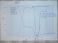
My guess is that bands 7 and 8, 2kcps to 4kcps, are 12-14dB down because of ear sensitivity. The other bands have only light loss.
I know a former librarian at AT&T. Cast-off in the post divestiture shuffle, of course. The dregs of AT&T are not keeping secrets. They just don't know or care.
Without the important variable; frequency?
My guess is that bands 7 and 8, 2kcps to 4kcps, are 12-14dB down because of ear sensitivity. The other bands have only light loss.
I know a former librarian at AT&T. Cast-off in the post divestiture shuffle, of course. The dregs of AT&T are not keeping secrets. They just don't know or care.
> reasoning over the resistor arrangement for these 10 potentiometer circuits
Without the important variable; frequency?
My guess is that bands 7 and 8, 2kcps to 4kcps, are 12-14dB down because of ear sensitivity. The other bands have only light loss.
I know a former librarian at AT&T. Cast-off in the post divestiture shuffle, of course. The dregs of AT&T are not keeping secrets. They just don't know or care.
I was told you also need a license to get a copy of them. Technically what you are saying isn't what I've been told. I think you can be shown the schematics but you just can't be given a copy of them , at least over the internet.
Do you know which resistor network connects to each filter ? Like PRR i have been thinking along the lines of Fletcher Munson equal loudness curves but i cant make the resistor networks attenuation levels match up very well to the curves , maybe they used more than one pot value .
Do you know which resistor network connects to each filter ? Like PRR i have been thinking along the lines of Fletcher Munson equal loudness curves but i cant make the resistor networks attenuation levels match up very well to the curves , maybe they used more than one pot value .
Here are what the resistor network matches to what key / filter number :
An externally hosted image should be here but it was not working when we last tested it.
Do you know that "N" is definitely a voltage source as Homer Dudley was favouring controlling the outputs of the bandpass filters as in fig 6 of his patent application .
Do you know that "N" is definitely a voltage source as Homer Dudley was favouring controlling the outputs of the bandpass filters as in fig 6 of his patent application .
I do know about and have seen that patent (US2121142A) before and it seems that the control of the filters that are in schematics in the patent was never actually actually used.
There is a article that was published in 1939 that was put in the journal of the franklin institute and written by the people who designed the voder. This document is an in depth look into how the voder actually worked and did include some final schematics that were used when the Voder was actually built. The keyboard schematic in this article, do somewhat match up with the blueprints that bell labs have, except for how the keyboard schematic in the article is missing the voltage divider for each key, but everything else is basically identical. So I am sure the blueprints for the key circuits with the various resistor networks is the actual schematics used in the final design.
You can check out the Journal of the franklin institute article here : Franklin Institute article.pdf - Google Drive
I totally forgot to mention that there is a person who did build a clone of the voder : Replica of The Voder - YouTube
So I totally forgot I could ask him about what his keys audio levels are on the output, and what I found out from him, is every key has a different perceived audio level
He didn't implement the voltage dividers on each key, as this information wasn't available when he built his clone.
So I am guessing this solves the mystery somewhat of the voltage divider , except for why did the engineers pick these specific resistor values? and the mystery of each Potentiometer for each key, possibly having different values.
Thanks for the link in post 16 . The Franklin Institute journal provides the only photo I have seen that covers the other side of the exposed keys , the interesting side . Just a pity it is not super detailed when enlarged .
I have already seen that YouTube video thanks and I have also seen how incredibly difficult it is to play the Voder . Building it may be the easy part .
I have already seen that YouTube video thanks and I have also seen how incredibly difficult it is to play the Voder . Building it may be the easy part .
I may have an answer to why 1.5K resistors are put across the pots . If you make the pots ( I use the word pots but they look more like straight possibly wire wound potentiometer tracks ) 1K ohm then with a 1.5K resistor in parallel you end up with a 600 ohm output impedance which is a standard transmission line impedance to connect to the filters . As for the use of different resistor values in the attenuators I do not know all I can say is there combined resistance offers an approximate 800 ohm load to the sources .
- Home
- General Interest
- Everything Else
- Figuring out reason for various resistor values on Potentiometer circuits