I am just planning a single-ended stereo amp using a pair of Hammond 1627SE output transformers I have had around for 20 years.
Going to go with a single KT88 in triode mode.
Cathode bias, 355VDC across the tube, run about 110ma.
Looking for driver ideas, something a little more than the typical.
What do you think of this circuit in front of the KT88?
Aikido push-pull 12SN7.
I would likely add another stage in front to increase the gain.
Attachments
What do you think the grid bias will be on your KT88? About -35V? Maybe -40V?
Figure that out and then you will know how much signal voltage you need the driver stage to swing into the KT88's grid.
What audio source(s) will you be using? What output voltage will that produce? 2V RMS max? 1V RMS max? Less?
Once you know that, then you'll know how much gain the driver stage will need to provide.
If you have analog sources that put out 1V RMS (1.4V peak) max signal, and you have -40V grid bias on the KT88, then the minimum gain the driver must provide is 40/1.4 = 28.6X. Many people say you should double that to add 6dB extra gain, in case of recordings that are at too low a level, which means you'd want at minimum 50X gain.
If you want to add negative feedback, the driver stage will need to produce the gain needed to achieve that too. So if you apply 6dB NFB, you'll need to double the gain again. So now we're looking at 100X gain.
So design a driver stage (or combination of stages) that produces 100X gain (or 50X if no NFB will be applied), has nice low output impedance, and can sink enough current into the KT88-triode's load/Miller capacitance.
--
I am just planning a single-ended stereo amp using a pair of Hammond 1627SE output transformers I have had around for 20 years.
Going to go with a single KT88 in triode mode.
Cathode bias, 355VDC across the tube, run about 110ma.
Looking for driver ideas, something a little more than the typical.
What do you think of this circuit in front of the KT88?
Aikido push-pull 12SN7.
I would likely add another stage in front to increase the gain.
I've bought the Akido noval pcb from Glassware Audio to drive my parallel KT120 amp using Hammond SE1640 otp.
With 12AX7s the gain is 46 and output impedance 1238r so enough to drive the 120s.
The pcb is very high quality and accommodates a variety of tubes, but the 12AX7 is needed for highest gain. I haven't built or tested it yet as the mains transformers are weeks overdue.
Last edited:
What do you think the grid bias will be on your KT88? About -35V? Maybe -40V?
Figure that out and then you will know how much signal voltage you need the driver stage to swing into the KT88's grid.
What audio source(s) will you be using? What output voltage will that produce? 2V RMS max? 1V RMS max? Less?
Once you know that, then you'll know how much gain the driver stage will need to provide.
If you have analog sources that put out 1V RMS (1.4V peak) max signal, and you have -40V grid bias on the KT88, then the minimum gain the driver must provide is 40/1.4 = 28.6X. Many people say you should double that to add 6dB extra gain, in case of recordings that are at too low a level, which means you'd want at minimum 50X gain.
If you want to add negative feedback, the driver stage will need to produce the gain needed to achieve that too. So if you apply 6dB NFB, you'll need to double the gain again. So now we're looking at 100X gain.
So design a driver stage (or combination of stages) that produces 100X gain (or 50X if no NFB will be applied), has nice low output impedance, and can sink enough current into the KT88-triode's load/Miller capacitance.
--
Yes there will about 35V at the cathode. Wouldn't 12.3VAC RMS to the grid start causing it to draw current?
Looking at sources of maybe 1V RMS.
As I mentioned, I can certainly add another gain stage in front so the whole amp might have gain figure of 28-35db. The attached schematic above with the 4 x 12SN7 sections is not offering a lot of gain. Maybe 6X. I doubt I would be applying feedback.
The Aikido line stage is pretty flexible.
The first stage is what Merlin Blencowe calls a 'half-mu' stage, which yields about half the available mu of the triode used. Since 12SN7 has a mu of 20, gain of about 14 with cathode degeneration, I'd think a gain of about 7 would be a good guess.
What if the first stage was made from a triode with higher mu? How about 12AY7 or 5965, with a mu of about 40? Degenerated that would be about 28 or so, so you should get 25X gain. That would be just barely enough (1.4Vpk * 25 = 35Vpk).
12AX7 would give you gain of about 35X. Or get the octal Aikido pcb from Glassware and use a 6SL7 as the first tube and 6SN7 as the second. That would get you to 35V peak from 1.4V peak input with some room to spare, using that same Aikido circuit.
Glassware makes a noval version of the Aikido PCB, with a suggested usage being first stage 12AX7 and second stage 12AU7.
Aikido Octal 6SL7/6SN7 pre voltage out?
--
Last edited:
The Aikido line stage is pretty flexible.
The first stage is what Merlin Blencowe calls a 'half-mu' stage, which yields about half the available mu of the triode used. Since 12SN7 has a mu of 20, gain of about 14 with cathode degeneration, I'd think a gain of about 7 would be a good guess.
What if the first stage was made from a triode with higher mu? How about 12AY7 or 5965, with a mu of about 40? Degenerated that would be about 28 or so, so you should get 25X gain. That would be just barely enough (1.4Vpk * 25 = 35Vpk).
12AX7 would give you gain of about 35X. Or get the octal Aikido pcb from Glassware and use a 6SL7 as the first tube and 6SN7 as the second. That would get you to 35V peak from 1.4V peak input with some room to spare, using that same Aikido circuit.
Glassware makes a noval version of the Aikido PCB, with a suggested usage being first stage 12AX7 and second stage 12AU7.
Aikido Octal 6SL7/6SN7 pre voltage out?
--
I was under the impression that first and second stages would be best if they pull identical currents. Kinda marrying Aikido to CCDA (constant current draw amplifier). I do like your idea though.
The Aikido is unusual and I cannot see the need to add anything to it.
As I said earlier, using 12AX7s you have enough gain to drive your output stage and the output impedance is lower at under 1300r.
(overall gain is about 40x taking into account the .99 gain of the output stage)
The excellent PSRR is also a bonus.
As I said earlier, using 12AX7s you have enough gain to drive your output stage and the output impedance is lower at under 1300r.
(overall gain is about 40x taking into account the .99 gain of the output stage)
The excellent PSRR is also a bonus.
The Aikido is unusual and I cannot see the need to add anything to it.
As I said earlier, using 12AX7s you have enough gain to drive your output stage and the output impedance is lower at under 1300r.
(overall gain is about 40x taking into account the .99 gain of the output stage)
The excellent PSRR is also a bonus.
Is there a drawing available or do I have to make a purchase to see it?
Aikido is so 08/15. (German expression for something so ordinairy its bland)
EC86 10M45S plate loaded will give you that 40x gain with just one tube. just glancing over the curves. A friend of mine who has built dozens of amplifiers recently went on the record its one of the nicest if not the nicest driver tube he has ever heard. But that was in a 6B4G SE so YMMV
As usual the russkies made a copy of that tube, but because its not well known they have trouble offloading the stocks of those. You can pick up the millspec variant for about 2USD each. PN is :
6S3P-EV
Schematics and more here:
Aikido Cascode
The schematic of the line amp is not shown although not much different. Some components values are different, mainly depending on tubes used.
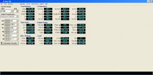
I plugged your values into SEAmp Cad (the app is available from Glassware as well) - see image.
4.24wt @ 5% 2nd harmonic distortion, 26.4v at the cathode so 52v p-p input needed. 240R cathode resistor. KT88 running at 90% dissipation.
Aikido Cascode
The schematic of the line amp is not shown although not much different. Some components values are different, mainly depending on tubes used.
I plugged your values into SEAmp Cad (the app is available from Glassware as well) - see image.
4.24wt @ 5% 2nd harmonic distortion, 26.4v at the cathode so 52v p-p input needed. 240R cathode resistor. KT88 running at 90% dissipation.
Attachments
Aikido is so 08/15. (German expression for something so ordinairy its bland)
EC86 10M45S plate loaded will give you that 40x gain with just one tube. just glancing over the curves. A friend of mine who has built dozens of amplifiers recently went on the record its one of the nicest if not the nicest driver tube he has ever heard. But that was in a 6B4G SE so YMMV
As usual the russkies made a copy of that tube, but because its not well known they have trouble offloading the stocks of those. You can pick up the millspec variant for about 2USD each. PN is :
6S3P-EV
Is there a simple drawing for the circuit? I have not used the 10M45S yet. My interest is piqued.
I have to agree that the EC86 is a perfect tube for this application. I drive an EML mesh plate 2A3 with mine: 1.8V LED bias, CCS on plate; Ep = 150V Ip= 5mA. The RFT are dirt cheap and sound great.
Aikido is so 08/15. (German expression for something so ordinairy its bland)
So you have heard one? if not how are you qualified to comment?
Is there a simple drawing for the circuit? I have not used the 10M45S yet. My interest is piqued.
The K&K Two Terminal Constant Current Source works well, sounds great, and is easy to implement.
Aikido is so 08/15. (German expression for something so ordinairy its bland)
EC86 10M45S plate loaded will give you that 40x gain with just one tube. just glancing over the curves. A friend of mine who has built dozens of amplifiers recently went on the record its one of the nicest if not the nicest driver tube he has ever heard. But that was in a 6B4G SE so YMMV
As usual the russkies made a copy of that tube, but because its not well known they have trouble offloading the stocks of those. You can pick up the millspec variant for about 2USD each. PN is :
6S3P-EV
Schematics and more here:
Aikido Cascode
The schematic of the line amp is not shown although not much different. Some components values are different, mainly depending on tubes used.
I plugged your values into SEAmp Cad (the app is available from Glassware as well) - see image.
4.24wt @ 5% 2nd harmonic distortion, 26.4v at the cathode so 52v p-p input needed. 240R cathode resistor. KT88 running at 90% dissipation.
4W, gee that's 12% efficiency? Maybe I should consider an EL34.
if you increase B+ to 400, change to fixed bias and reduce Ima to 90, the power increases to 7.6w @6.8% 2nd harmonic, 0% 3rd harmonics.
With two KT88 in parallel, power is 10w @4.5%
EL34 according to the calculator:
7.3w, 10%, 355v, 65ma fixed bias. Two in parallel gives about 10w,
With two KT88 in parallel, power is 10w @4.5%
EL34 according to the calculator:
7.3w, 10%, 355v, 65ma fixed bias. Two in parallel gives about 10w,
I have to agree that the EC86 is a perfect tube for this application. I drive an EML mesh plate 2A3 with mine: 1.8V LED bias, CCS on plate; Ep = 150V Ip= 5mA. The RFT are dirt cheap and sound great.
RFT was never renowned for its super high quality, it was higher quality than most of the Russian stuff, but not on par with what their relatives made up in Hamburg (Valvo). Their EL34 is very decent and miles ahead of the current JJ EHX or Shuguang production.
I have a drawer full of the gold pin EC86/88 and something struck me as odd, Telefunken made its own version of E86C called EC806s which is weird because Telefunken denotes a frame grid tube with the s on the End, however the plain EC86 is already a frame grid.
I would drive the EC86 somewhat harder than 10mA to get slightly better linearity out of it, besides that your operating point is spot on. And those ruskies are seriously tempting for me at the moment cause they are dirt cheap.
Oh and to answer another question, I have listened to Akaido like topologies, however still no circuit with values has been posted. So its apples and oranges at this time.
Is it as simple as using a red LED at the cathode of the EC86, and a 1k pot as the current setting resistor for the 10M45S? B+ voltage above the CCS - what range would be appropriate? Keep in mind I have not used either of these devices, so bear with me.
You need to also include a 1K grid stopper for the 10M45S. And a 2K2 or thereabouts carbon comp on the grid of the EC86. A 47-100R carbon comp between the anode and the CCS can be used to hedge against Oscillation in the UHF region.
And sometimes it is required to RC filter de B+ supply to get the voltage above the CCS at about 300VDC. You then drop about 150V across the 10M45S. This R is about 100 Ohms per volt of drop. So say your coming down from 400 you need a 10K resistor for the RC filter section with a 3W wattage rating because the resistor sees about 1W of dissipation.
Current set resistor is 330R for about 10mA +-1mA you can also use a parallel combination of 680R and a 1K pot. This way nothing breaks if the pot goes open circuit for some reason.
At 150V and 10mA working point your looking at about -1.8V grid bias, measured with the MK1 eyeball. A run of the mill red LED will give you a drop of about 1.8V at that current.
- Home
- Amplifiers
- Tubes / Valves
- Driver stage for SE KT88