Not proposing more taps to the usual 0-4-8-16 ohm single winding..
Instead additional (separate) windings matched for bass, mid, and treble filter drives.
Since tube amps enjoy the luxury of hi voltage OT's.. perhaps this lends to the idea??
Jim
Instead additional (separate) windings matched for bass, mid, and treble filter drives.
Since tube amps enjoy the luxury of hi voltage OT's.. perhaps this lends to the idea??
Jim
Last edited:
With the bass drive primarily,
Just upgraded my PP amp from 6BQ5 outs to 6GM5's. Upgraded PT to keep up w/ B+ current demand. As such, this increased potential distorted my bass drivers, while the above freq's were still clean and clear...
So this started me thinking that a separate higher voltage tap could be wound to secondary that could be dedicated to Bass drive. Since speaker deflection of woofers requires much more delta V than mids or trebs, then it should have it's own winding...
Jim
....speaker deflection of woofers requires much more delta V than mids or trebs, then it should have it's own winding...
What do you mean by that?
"What do you mean by that?"
It's been discussed here that to optimize speaker output, one must match impedance of OT to speaker coil...
Further-
I suggest that the largest recipient of OT current are the woofers- as such, perhaps they should be isolated from the other 'parasitic' drains?
For this discussion, I define 'parasitic' as drain from crossover for other frequency drivers, which, IMO compromises the optimal performance.
I believe an isolated winding for mid/ treb outs could be beneficial to 'free up' the the primary winding dedicated to the woofers.
Spreading the think,
Jim
You said "delta V", which I thought was Voltage.
Now you say "largest recipient of OT current".
Not clear what you want to "free up". Maybe you have special insight into electricity.
Now you say "largest recipient of OT current".
Not clear what you want to "free up". Maybe you have special insight into electricity.
You said "delta V", which I thought was Voltage.
Now you say "largest recipient of OT current".
Voltage shifts into a static impedance results in the same current map.
While a 'static impedance' is not characteristic of speaker windings, this topic is outside of what the main point is-imo.
Jim
Now you say "largest recipient of OT current".
Voltage shifts into a static impedance results in the same current map.
While a 'static impedance' is not characteristic of speaker windings, this topic is outside of what the main point is-imo.
Jim
Just upgraded my PP amp from 6BQ5 outs to 6GM5's. Upgraded PT to keep up w/ B+ current demand. As such, this increased potential distorted my bass drivers, while the above freq's were still clean and clear...
I would suggest that in "upgrading" from 6BQ5s to 6GM5s you nerfed the performance of you amp and you need to revisit what you did and correct any issues.
What you point out is the focus of this thread-
As stated previous-
PT was upgraded for this new manifest; upper frequency portion of sound was retained of good quality reproduction- but lower frequencies were compromised.
Whilst I've not delved into the background of woofers specs, this topic came to me as a possibility, so then this prompt of discussion on a forum from which I've learn much.
Jim
Last edited:
To be clear-
I've supplanted 4 different versions of design into same chassis/ iron (except stated PT).
This latest rendition is the only one that has shown weakness in the aforementioned area.
All suggestions appreciated-
Jim
I've supplanted 4 different versions of design into same chassis/ iron (except stated PT).
This latest rendition is the only one that has shown weakness in the aforementioned area.
All suggestions appreciated-
Jim
Not proposing more taps to the usual 0-4-8-16 ohm single winding..
Instead additional (separate) windings matched for bass, mid, and treble filter drives.
Since tube amps enjoy the luxury of hi voltage OT's.. perhaps this lends to the idea??
Jim
It's been done.
I am using exactly that because my amps have multiple windings at 25V + ct, 16 ohms then another NFB winding (70v) and another CT 70V winding + a 115v winding at the end of that.
The high voltage windings typically match high impedance tweeters and you basically use the OPT as part of the cross over network with bi or tri wiring for the whole lot.
The result is just outstandingly and incredibly successful, but you will only find it on certain high quality PA transformers from the 60s.
Part of the idea came from pages from Tubcad.
Matching of loads is done principally by voltages, not by hard and fast rules on damping factor (that old nonsense), and theoretical "what's marked on the box" type of impedance matching, because speaker driver loads are just about anything BUT what they claim to be. 🙄
Before Broskie became obsessional about PSRR, and made a webzine that is a mix of stupidity with a bad search engine, but some flashes of inspiration, I take most of what he writes with a large pinch of salt.
This was following advice from the guy who runs electraprint.
I will try to find my archives that were actually useful.
After some long exchanges with D G, we conceded that output transformers clearly behave very differently when all windings are loaded, compared with just 2 taps, especially regarding HF distortion.
Sadly most of the A-philes, don't get any of this, and are horrified when you do things which they either have never thought of, or consider in some way "extremely risky" or insist on using nice home made wiring harnesses from 50m lenths of cable, which don't cost zillions to purchase...
I can take Broskies obsession about PSSR.
But would you care to show some examples of claimed stupidity?
Just curious
But would you care to show some examples of claimed stupidity?
Just curious
And how does the OPT act as part of the crossover network?It's been done.
The high voltage windings typically match high impedance tweeters and you basically use the OPT as part of the cross over network with bi or tri wiring for the whole lot.
Matching of loads is done principally by voltages, not by hard and fast rules on damping factor (that old nonsense)
So you are scaling the secondary windings to get approximately equal output from each driver so you don't have to pad any down?
Is this the article in question?
B-Wiring Part Two
Just because "we can do it" doesn't mean it's particularly useful.
I've been researching this since posting the thread-
Related topics linked below are Bi-Wiring & Bi-Amping, but nothing specific so far to what I'll call "Bi-Coiling".
How to Bi-Wire and Bi-Amp Your Speakers — Sewell Direct
Why Do Quality Speakers Have Two Input Terminals? - Definitive Technology
Signature SE Pair - Morrow Audio
Last link showing speakers that have separate inputs for low and high frequencies. This could allow something as simple as an external crossover, or Bi-Amping or -Wiring.
Quote:
"Is this the article in question?
B-Wiring Part Two"
This was interesting, as it gave different definition to Bi-Wiring... perhaps Part One of this was more conventional like the links I posted above? The schematics shown in that article of hooking multiple speakers to different impedance taps of a single coil still begs the question (in my mind) of possible parasitic effect of different speaker load graphs... (ie- freq vs delta Z of most all speakers) attached to mutually used segments of same single coil.
Maybe this is negligible since it's not discussed anywhere that I've seen yet-
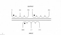
I'm working on having a pair of OT's made to the diagram pic below. If a single 16 ohm can fit, then (2) 8's should also. If 0-4-8, and 0-16 OT setup was applied to layouts shown in above TubeCad article, what (if any) would be the downside compared to the single 0-4-8-16?
IMO, separating the coils produces more possibility of gain than loss. When they arrive, next hurdle will be how to test to quantify this.
Jim
Related topics linked below are Bi-Wiring & Bi-Amping, but nothing specific so far to what I'll call "Bi-Coiling".
How to Bi-Wire and Bi-Amp Your Speakers — Sewell Direct
Why Do Quality Speakers Have Two Input Terminals? - Definitive Technology
Signature SE Pair - Morrow Audio
Last link showing speakers that have separate inputs for low and high frequencies. This could allow something as simple as an external crossover, or Bi-Amping or -Wiring.
Quote:
"Is this the article in question?
B-Wiring Part Two"
This was interesting, as it gave different definition to Bi-Wiring... perhaps Part One of this was more conventional like the links I posted above? The schematics shown in that article of hooking multiple speakers to different impedance taps of a single coil still begs the question (in my mind) of possible parasitic effect of different speaker load graphs... (ie- freq vs delta Z of most all speakers) attached to mutually used segments of same single coil.
Maybe this is negligible since it's not discussed anywhere that I've seen yet-
I'm working on having a pair of OT's made to the diagram pic below. If a single 16 ohm can fit, then (2) 8's should also. If 0-4-8, and 0-16 OT setup was applied to layouts shown in above TubeCad article, what (if any) would be the downside compared to the single 0-4-8-16?
IMO, separating the coils produces more possibility of gain than loss. When they arrive, next hurdle will be how to test to quantify this.
Jim
Attachments
Last edited:
> . If a single 16 ohm can fit, then (2) 8's should also. ...., what (if any) would be the downside compared to the single 0-4-8-16?
Twice the winding resistance.
Remember a wire has width as well as length.
Twice the winding resistance.
Remember a wire has width as well as length.
I've been researching this since posting the thread-
Related topics linked below are Bi-Wiring & Bi-Amping, but nothing specific so far to what I'll call "Bi-Coiling".
Signature SE Pair - Morrow Audio
Last link showing speakers that have separate inputs for low and high frequencies. This could allow something as simple as an external crossover, or Bi-Amping or -Wiring.
Maybe this is negligible since it's not discussed anywhere that I've seen yet-
if a single 16 ohm can fit, then (2) 8's should also. If 0-4-8, and 0-16 OT setup was applied to layouts shown in above TubeCad article, what (if any) would be the downside compared to the single 0-4-8-16?
I have had proveable success each and every time using a config no transistor amp can do.
It's to my mind one of the major advantages of a valve amp, unless the tranny amp has outputs simultanously available to drive 100v line (non comsumer-industrial amps).
I keep some old high quality Bogen 100V line transistor matching transfos for exactly that.....
If you have already got 0 4 8 16 on a valve output transformer, you don't bother with the 8 ohm tap.
You wire one pair of speakers to the 0-4 tap, and the other pair to the 4-16. (The 4 ohm tap is the CT of the 16 ohm full winding anyhow.)
Many nominal speakers in any case drop from a nominal 6-8 ohms to around 4, so this provides the right match to the amp anyhow, but it's considered a highly unorthodox approach because so many people are set in their ways.
In all my tests bi wiring against single wiring speakers, the (Neumann studio) microphones of the scan test picked up the biwired or bi-speakered test as by far the best.
I was suprised to see such measurable differences as clearly visible on audio spectra when analysing the recordings with FFT.
I wasn't expecting that.
On a back-back test using a pair of Vandersteen amps with my old AB2 KT8 valve amp, and then powering up a pair of JBLs as the 2nd pair (couldn't be done with the tranny amp present at the same test place) we found the most fantastic result was obtained using the 4 speakers compared with just a pair of JBL or a pair of Vandersteen.
We spent a week doing all these tests, with a DAW assisted by a DSP, so they are not fake or subjective, and can be reproduced.
Last edited:
Before Broskie became obsessional about PSRR, and made a webzine that is a mix of stupidity with a bad search engine, but some flashes of inspiration, I take most of what he writes with a large pinch of salt.
Would you care to show some examples of claimed stupidity?
- Home
- Amplifiers
- Tubes / Valves
- Multiple tap OT's??