Progress is a team sport my friend... all comments and thoughts are welcome.I’ll keep potentially distracting comments or suggestions to a minimum
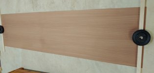
The veneer arrived yesterday. This is the first time I have worked with sapele veneer. The sheet I have is 24" x 96", with PSA backing (peel and stick). This quarter-sawn veneer looks quite nice, and will offer some variety in my living room. Some woodworkers poo-poo PSA backed veneer, and for really large projects like dining tables, conference tables, large display cabinets, it is better to use paper backed veneer and contact cement... But for the relatively small sizes of speaker cabinets (in comparison to large furniture), I think PSA has enough adhesion and is very convenient.
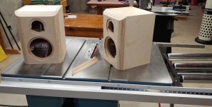
I made a little more progress this morning. I cut the bevel on the top edge.
The next step is to sand the whole cabinet with 80 grit, apply some bondo to the low spots and holes, then sand smooth.
j.
Attachments
I use paper backed veneer too, I'm not yet patient enough to use regular veneer yet nor do I have room for a vacuum press. I used contact adhesive on my first veneered speaker project and I found it to be unpleasant. Cleaning the roller was the worst part, I used water-based adhesive and it would take 20 minutes of hot water and a scrubby to get it clean and by the end of the job the roller was no longer flat. On my next build I switched to PSA backed and it was a dream. No rolling, not waiting and no cleanup. The price works out nearly the same considering the cost of the adhesive and a new roller every time. The way I figure it I'm building for me and not to hand down over the generations so if it delaminates in 50 years it won't matter. I use Supporting Woodworkers for 17 Years! - Exotic Wood Veneer, Vacuum Press Systems, Tools and Supplies and I'm quite happy with the service. Once it warms up I plan on building new office furniture and I will be using Sapele veneer on the cabinets.
hifijim,
Those round-overs look really well done, nice job!
For a cabinet with such large round-overs, what would you take as the baffle width for designing the XO?
Those round-overs look really well done, nice job!
For a cabinet with such large round-overs, what would you take as the baffle width for designing the XO?
Last edited:
zman1
Why it's important to quantify the baffle width for designing the XO? The frequency response, baffle step loss and diffraction ripple will appear in the measurements which is more accurate data to design a XO than knowing the exact baffle width.
Why it's important to quantify the baffle width for designing the XO? The frequency response, baffle step loss and diffraction ripple will appear in the measurements which is more accurate data to design a XO than knowing the exact baffle width.
Last edited:
YSDR, agree, and hifijim is taking measurements all the way.
My question was from a curiosity/learning perspective, specially for making bevels larger on existing designs. But taking actual measurements would be the correct way forward there too. 🙂
My question was from a curiosity/learning perspective, specially for making bevels larger on existing designs. But taking actual measurements would be the correct way forward there too. 🙂
I made a baffle diffraction simulation with Vituixcad and I showed it in the first post. Since this is an active design, I can compensate for the baffle step easily. But upper-level diffraction (i.e. above 1.5 kHz) is difficult or impossible to compensate for with DSP eq... So my thought is to just minimize diffraction as much as possible. The simulations show that as the radius increases, diffraction effects drop. By the time the radius increases to 30mm or more, diffraction has been almost completely mitigated. Nearly any baffle shape results in a good response if the edge radius is 30 mm or more… rectangular, trapezoidal, elliptical, square, circular, all are good. Bottom line, even though I am using DSP EQ, I think it is important to simulate the baffle to ensure it does not have a diffraction problem which would be difficult to correct later.
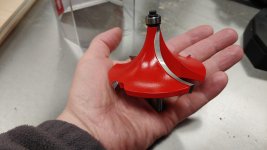
Here is a picture of the bit I use… It is a Freud bit, and it performs very well. It is the "Freud 1-1/2" Radius Rounding Over Bit, 1/2" Shank (Quadra-Cut) (34-140)". Highly recommended. When using this bit, we need to use a powerful router and a speed of no more than 12000 RPM. It is so large, it does not fit in the standard base plate of my router table... I had to make a special base plate from plywood with a extra large hole.
j.
Attachments

Last edited:

I made some progress today, although I spent much of the morning giving my workshop a good cleaning. My wife and I both share the workshop, and she gets annoyed when everything is covered in a thick layer of sawdust. Most of my machines have dust collection, but routers are just the worst… It would have to be done before the finish work anyway, since a dusty workshop and varnish do not combine well… I managed to get veneer applied to the back and top of the cabinets.
I wanted to pull on the line of thought that zman and YSDR brought up. Baffle edge diffraction. We all know it affects the frequency response of drivers, mainly above 1500 Hz. I believe that that cabinet edge diffraction has an effect that goes beyond its impact on frequency response. It affects the 3-dimensional quality of the music. This shows up mostly on music that has preserved that aspect through the recording/reproduction process. So there is no doubt that I was going to build a low diffraction cabinet for this system. But there is another advantage to a low diffraction cabinet: It simplifies the DSP filter design process.
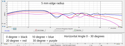
One of the steps in designing a DSP filter is EQ’ing the drivers to be flat in the pass band and for at least one octave beyond the crossover frequencies. The drivers should be EQ’d to the point where they appear flat when viewed with 1/6th octave smoothing. However, the response we want to EQ is not the on-axis response, but the listening window response. Without getting into too many details, the listening window response is the average of many responses across +/- 30 degree horizontal and +/- 10 degree vertical.
The first graphic shows a simulation of my baffle with a 5mm edge radius. We can see the response at 0, 10, 20, and 30 degrees horizontal. This is purely the baffle diffraction response, thus it is the response we would measure if we were using a perfectly flat driver. There is a lot of variation from 2k to 8k in the range of +/- 1.5 dB. When averaged across the listening window, it might turn out to be mostly flat, i.e., all those peaks and nulls might cancel each other out. But every time we make a DSP filter adjustment, we would have to re-measure the entire listening window again. The diffraction makes it difficult to identify driver response anomalies. We will have to make sure that any narrow band EQ we are applying is actually correcting a driver anomaly, not correcting a diffraction response (we do not want to do that).
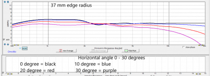
The second graphic shows the same simulation but with a 37mm edge radius. Now we see there is much less variation at 0, 10, 20, and 30 degrees horizontal. Other than the expected high frequency roll off above 8k, the curves are very similar. The simulation tells us that the on-axis curve will be nearly the same as the listening window curve. Once we verify that with our preliminary measurements, it frees us to simply use the on-axis curve as a proxy for the listening window. As we make DSP filter changes, we can simply make an on-axis response measurement. We can have confidence that whatever change we see in the on-axis response will be reflected in the listening window response. I like this freedom. It means I can make a preliminary set of off-axis responses from 0 to 90 degrees horizontal, and then do all my development work without having to change microphone or speaker position. Then at the end, I can make a final full set of off-axis responses 0 to 90 degrees horizontal.
j.
I wanted to pull on the line of thought that zman and YSDR brought up. Baffle edge diffraction. We all know it affects the frequency response of drivers, mainly above 1500 Hz. I believe that that cabinet edge diffraction has an effect that goes beyond its impact on frequency response. It affects the 3-dimensional quality of the music. This shows up mostly on music that has preserved that aspect through the recording/reproduction process. So there is no doubt that I was going to build a low diffraction cabinet for this system. But there is another advantage to a low diffraction cabinet: It simplifies the DSP filter design process.
One of the steps in designing a DSP filter is EQ’ing the drivers to be flat in the pass band and for at least one octave beyond the crossover frequencies. The drivers should be EQ’d to the point where they appear flat when viewed with 1/6th octave smoothing. However, the response we want to EQ is not the on-axis response, but the listening window response. Without getting into too many details, the listening window response is the average of many responses across +/- 30 degree horizontal and +/- 10 degree vertical.
The first graphic shows a simulation of my baffle with a 5mm edge radius. We can see the response at 0, 10, 20, and 30 degrees horizontal. This is purely the baffle diffraction response, thus it is the response we would measure if we were using a perfectly flat driver. There is a lot of variation from 2k to 8k in the range of +/- 1.5 dB. When averaged across the listening window, it might turn out to be mostly flat, i.e., all those peaks and nulls might cancel each other out. But every time we make a DSP filter adjustment, we would have to re-measure the entire listening window again. The diffraction makes it difficult to identify driver response anomalies. We will have to make sure that any narrow band EQ we are applying is actually correcting a driver anomaly, not correcting a diffraction response (we do not want to do that).
The second graphic shows the same simulation but with a 37mm edge radius. Now we see there is much less variation at 0, 10, 20, and 30 degrees horizontal. Other than the expected high frequency roll off above 8k, the curves are very similar. The simulation tells us that the on-axis curve will be nearly the same as the listening window curve. Once we verify that with our preliminary measurements, it frees us to simply use the on-axis curve as a proxy for the listening window. As we make DSP filter changes, we can simply make an on-axis response measurement. We can have confidence that whatever change we see in the on-axis response will be reflected in the listening window response. I like this freedom. It means I can make a preliminary set of off-axis responses from 0 to 90 degrees horizontal, and then do all my development work without having to change microphone or speaker position. Then at the end, I can make a final full set of off-axis responses 0 to 90 degrees horizontal.
j.
Attachments
hifijim,
Thanks for sharing the sims. The 37mm radiused baffle does look much better in this regard.
The veneer on the cabinets are looking good.
And referring to the image of your round-over bit in #26 of this thread - that is by far the largest round over bit I have ever seen. 🙂
Thanks for sharing the sims. The 37mm radiused baffle does look much better in this regard.
The veneer on the cabinets are looking good.
And referring to the image of your round-over bit in #26 of this thread - that is by far the largest round over bit I have ever seen. 🙂
I think it is one of the largest router bits made. It is a bit scarry when it spools up to 10,000 rpm. 😱
If I did not have the tools to make a 37 mm radius roundover, I would cut a 45 degree bevel and then sand it to a round shape. It is more time consuming (maybe), but it is definitely cheaper...
By the way, Vituixcad has great baffle simulation features.
If I did not have the tools to make a 37 mm radius roundover, I would cut a 45 degree bevel and then sand it to a round shape. It is more time consuming (maybe), but it is definitely cheaper...
By the way, Vituixcad has great baffle simulation features.
There isn't a huge difference in the effectiveness of a chamfer vs a roundover. Bigger is better for both, a large chamfer beats a small roundover.
Here is a comparison of the simulated effects of a chamfer, roundover, 13mm step and flush connection of a woofer to a baffle. The outer edge of the baffle had a 36mm roundover in all cases so this is a fair comparison.
The vertical chamfers on Jim's baffle perform a useful function too 🙂
1m
With off axis angles
Thanks - Until now I had never seen a simulation comparing a bevel to a roundover. I had assumed they were basically equivalent, but I was never certain.
By the way, Vituixcad has great baffle simulation features.
I don't want to send your thread off-topic, but I just wanted to comment.
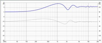
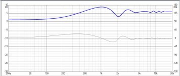
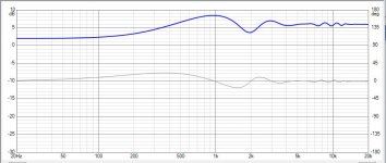
So far I've only tried out VituixCAD's diffraction module and I'm disappointed with it because something in the algorithm is not giving the same results as the other well know programs. Specifically, the correlation above about 1000Hz between the major programs is very good but below that, VituixCAD's BD response varies with the mic distance such that the baffle step loss goes from just under 6db at 3m to just 4db at .5m. Pic 1 below at .5m. Pic 2 at 1m and pic 3 at 3m.
Unless there's some new info about baffle step loss that I'm not aware of, I see this as potentially a serious enough problem for me to give the module a pass most of the time.
Attachments
Now that is very interesting... It does not impact me in the way I use this tool, but it is interesting.
The fact that Vituixcad is making some kind of calculation based on mic distance makes me suspect the algorithm is compensating for the near-field effect.... perhaps?
I measure the low frequency response of woofers and mids in three ways: (1) outdoor groundplane, (2) in the listening position, and (3) near field. I use all three to assemble a composite best-estimate of anechoic response and a composite best estimate of in-room response.
I've done a compound 30 degree chamfer on the tweeter and mid and a 45 degree on the woofers. Because it is on both the vertical and horizontal plains the width at very top of the enclosure was about 3.5 inches. I didn't even try to chamfer the top. It also required a lot of extra layers 2 inch by 3/4 inch MDF glued to the inside of the sides as sacrificial material. The chamfer was so wide at the tweeter I didn't bother with a second chamfer. Who knows if it worked or not.
Jim,
This brings up a question I had, with a 1.5 inch baffle and 3/4 inch sides how thin did it get on the front corners after the 1.5 inch round over? My concern when I see these huge round overs recommended (sometimes > 3 inches) what happens to the structure of the enclosure?
Jim,
This brings up a question I had, with a 1.5 inch baffle and 3/4 inch sides how thin did it get on the front corners after the 1.5 inch round over? My concern when I see these huge round overs recommended (sometimes > 3 inches) what happens to the structure of the enclosure?
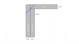
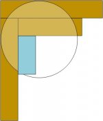
with a 1.5 inch baffle and 3/4 inch sides how thin did it get on the front corners after the 1.5 inch round over?
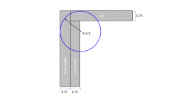
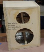
The inner baffle is completely encompassed by the side and top panels. The outer baffle overlays on the inner baffle and the edges of the sides and top. This provides a lot of glue surface. As you can see in the graphic, the 1.5 inch roundover leaves quite a bit of material, and a lot of glue surface area. The 45 degree bevel on the top leaves less material, but there is still a glue joint along the full 0.75 inch thickness of the panel.
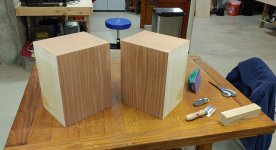
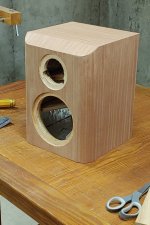
I was able to get one of the cabinets fully veneered. Getting the veneer trimmed flush and the curves and the bevel is "challenging"... I am a veneer newbe, and I struggled with this all afternoon. The second cabinet will be easier (trying to be optimistic). I definitely needed a beer when I was done.
Attachments
Thanks for the explanatory graphics on the round over and chamfer depth relative to corner thickness. You're making following this thread too easy!🙂
Last edited:
I found a Veritas Flush Plane to be very helpful for this sort of thing, as well as many other's if you have or want to get one. Or a really sharp chisel, but that can be risky, for me at least 🙂I am a veneer newbe, and I struggled with this all afternoon. The second cabinet will be easier (trying to be optimistic).
The inner baffle is completely encompassed by the side and top panels. The outer baffle overlays on the inner baffle and the edges of the sides and top. This provides a lot of glue surface. As you can see in the graphic, the 1.5 inch roundover leaves quite a bit of material, and a lot of glue surface area. The 45 degree bevel on the top leaves less material, but there is still a glue joint along the full 0.75 inch thickness of the panel.
I was able to get one of the cabinets fully veneered. Getting the veneer trimmed flush and the curves and the bevel is "challenging"... I am a veneer newbe, and I struggled with this all afternoon. The second cabinet will be easier (trying to be optimistic). I definitely needed a beer when I was done.
Funny, I just made a similar drawing. My concern is if I have 1.5 inch baffle and cut the corners I don't have a 1.5 inch baffle anymore, at best there is maybe 7/8 on the very corner and maybe less on the side. The blue strip glued to the inside helps my OCD.
Attachments
- Home
- Loudspeakers
- Multi-Way
- New active Satori Textreme