Except for one member here, no?This DAC performance is way beyond any audibility threshold.

Well for ME the okto DAC 8 pro would, with a bit of fineagling to do I2S to SPDIF conversion in my miniDSP give me a couple of things that I want but don't need. I could almost justify that on convenience even if it didn't sound any better.
Saw pics of the inside of that dac, recognize the circuit, layout looked pretty good compared to some.
I bet the layout still wasn't as good as this.
Last edited:
We either listen to the voltage of the amplifier (note the subject is the amplifier) or the current of the amplifier.
I thought we listen to the acoustic output of the speakers. Why don't you stick to selling your speakers rather than the nonsense theories? I have no problem with what you sell it could be very fine to many users and make them very pleased. If someone comes here to learn some actual theory you provide (less than) little.
It must be a part of the marketing message/strategy. It just adds that little needed wift of mystique if the product itself isn't interesting enough.
//
//
Well, going back to a few facts - 99% of the power from your amp goes to heating up the loudspeaker drive unit voicecoils. The remaining 1% is the acoustic output.
Well, going back to a few facts - 99% of the power from your amp goes to heating up the loudspeaker drive unit voicecoils. The remaining 1% is the acoustic output.
Yes, and in fact, the average modern driver is not even 0.5%.
OK, unlike others here, let us take your statement to the next level and take what you say seriously, which I do. Thanking you in advance for allowing me to respond:
Define "power" and define "acoustic output" - what part of the voice coil dissipates the heat and what part does not?
If the impedance is 10 Ohm @ 1KHz and the voltage is 10V, and the DC Resistance (Re) is 6R, then what is the dissipation in watts?
This is the "power from your amplifier" that you refer to.
Can a current be impeded by an impedance that does not dissipate heat? How?
If something impedes current, must it not have a value in Ohm?
Why did Neville Thiele measure "volts" using the "constant current" method and using Re as the baseline/reference converted "volts" into a back-EMF impedance? He added the two and had a total impedance curve. This was his preferred method (the other was "constant voltage").
Oops, did I just say "back-EMF impedance"?
Verboten!
That expression seems to have been censored by participants here by shouting it down. Yet Thiele did it sixty years ago!
EDIT: Let us call it the "excess" impedance above the Re and I am open to calling it something else.
At least, can we discuss it?
Last edited:
That last post was an opportunity to respond to somebody who made a valid statement and I felt that it needed to be responded with by actually asking a question that requires a technical answer, what is the dissipation in watts and why it is not 10 Watt? In fact, it is less than that.
actually asking a question that requires a technical answer
It would be nice if you presented this with a simplified circuit and an analysis with complex phasors. The power dissipated would be determined by the real part of the conjugate of the voltage times the current (as complex quantities).
"If the impedance is 10 Ohm @ 1KHz and the voltage is 10V, and the DC Resistance (Re) is 6R, then what is the dissipation in watts?
This is the "power from your amplifier" that you refer to.
Can a current be impeded by an impedance that does not dissipate heat? How?"
First question; I = V/Z, = 10/10 = 1A W = I^2.R = 6W
Second question; Yes it can, reactive components of impedance Xc and Xl do exactly that, they are measured in ohms and cause a phase shift of 90 degrees between V and I, and dissipate no heat, but in practice they always exhibit a small R in series with an inductor, and in parallel with a capacitor.
Last edited:
If all your power is dissipated in the DC resistance then what makes the sound?
DC resistance does waste power but to make noise some power must be converted into acoustic energy. A compression driver properly loaded can be 30% efficient. Home loudspeakers after the crossover may be 2% efficient. With a pad for some drivers this can drop an order of magnitude or a bit more.
DC resistance does waste power but to make noise some power must be converted into acoustic energy. A compression driver properly loaded can be 30% efficient. Home loudspeakers after the crossover may be 2% efficient. With a pad for some drivers this can drop an order of magnitude or a bit more.
Last edited:
Three classic standard texts cover all of this:
Frederick V Hunt, ElectroAcoustics, 1954
Leo Beranek, Acoustics, 1954
Harry F Olson, Acoustical Engineering, 1959
They covered the groundwork that underpinned Richard Small and Neville Thiele's classic series of papers on acoustic suspension loudspeakers in boxes.
These is absolutely no mystery regarding the low efficiency of acoustic suspension loudspeakers in boxes, which is typically from 0.5% to 1%. The only way of increasing efficiency significantly is by horn loading, when you might get up to 15% efficiency, at the price of much larger, more complex and expensive loudspeakers. The horn acts as an acoustical transformer, matching the mechanical impedance of the driver more efficiently to the air impedance.
First question; I = V/Z, = 10/10 = 1A W = I^2.R = 6W
Second question; Yes it can, reactive components of impedance Xc and Xl do exactly that, they are measured in ohms and cause a phase shift of 90 degrees between V and I, and dissipate no heat, but in practice they always exhibit a small R in series with an inductor, and in parallel with a capacitor.
Bravo!
We are talking plain Faraday induction.
So what would you call the 4 Ohm that does not generate heat?
Faraday impedance?
I called it "back-EMF impedance" and got attacked for calling it thus.
In my 'language' the 6 Ohm is the DC resistance Re of the voice coil, and the 4 Ohm part that takes it up to 10 Ohm is the "back-EMF impedance."
Why is my 'language' wrong?
If all your power is dissipated in the DC resistance then what makes the sound?
The real point is that the current that passes through the resistance of the voice coil has no phase shift. This is caused by the back-EMF that we can measure as a voltage (force) that works against the current of the amplifier and has an equivalent impedance of 4 Ohm.
What we end up listening to is in voltage terms what appears across the DC resistance. There is no phase shift across that part of the impedance, but it is impacted by the back-EMF so that the phase shift is no longer synced with the voltage of the amplifier. It also happens to be 100% proportional to the current of the amplifier. Hence we are listening to the current of the amplifier and not the voltage of the amplifier.
Test: Use a current sense resistor 0.1R and if the DC resistance 6 Ohm, use an ultra-low distortion amplifier, which needs a gain of 60.
See attachment 1.
Now you have recovered the Vre and this is the 'voltage' that the driver will try to reproduce as sound. What is important is to understand that Vre is proportional to the current of the amplifier and not the voltage of the amplifier. We are thus listening to the current of the amplifier, not its voltage. Yes, I am repeating what needs to be repeated.
1) Typically on 30% of the voltage of the amplifier is inside the magnetic gap. This voltage is ignored.
2) Yet 100% of the current of the amplifier is present in the gap and this is the actual force = F = BLi
3) Since Vre is the result of only the resistive part of the voice coil, this does not result in any phase shift, but the current phase has been changed by the excess impedance (in our example is 10R-6R=4R), as confirmed comments by other's comments here.
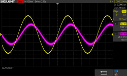
See attachment 2. Note Red and is Vre and the phase shift. Yellow is the voltage of the amplifier. Red is the current of the amplifier. Which one are we listening to? Can't be both.
So, what do we call that 4 Ohm?
Keep in mind that Thiele measured impedance, if he used 1A constant current, then he would have measured 4V = 4 Ohm. Yes, a voltage that is measured as an equivalent impedance. This is back (an opposing force) and an EMF is a voltage. Back-EMF is both a voltage that opposes and an impedance.
I was told by one unnamed person:
"Just because it looks like an impedance doesn't mean it is an impedance."
Really? If it's not an impedance, then what is it? Please explain?
We have a voltage source that "looks" like an impedance that produces a back-EMF, a force that opposes the current of the amplifier. Maybe it is what it "looks" because that is what it is.
Why have I been attacked for saying that 4 Ohm excess impedance can be called "back-EMF impedance."
What is wrong with that?
If the driver has any distortion, that will end up modulating the back-EMF impedance, this corrupts the Vre which is proportional to the entire 100% of current of the amplifier.
Since we are listening to the current of the amplifier, the corrupted current will feed back on itself as time smear. Measurements have shown that this leads to an increase in odd-order distortions. This feeding back on itself has already been mentioned by others (I am not alone here), such as Esa Merilainen in his Current-Drive book.
There is more distortion on Vre (that represents 100% of the current of the amplifier), than there is on the voltage of the amplifier, which I call Vt.
So we end up listening to a corrupted current of the amplifier.
Yes, current-drive means we can eliminate this because the load cannot corrupt the current. Indeed, now we shall see the 4 Volt exposed under current-drive conditions. But when you have current-drive, the current phase will always be zero. But the impedance here is converted back into volts, but it cannot corrupt the current.
I disagree with Esa, we are not going to convert the world to current-drive.
So we need to come up with better options, other than current-drive.
How do we lower distortion of the driver/speaker that corrupts the Vre and this feeding back on itself causing smeared out distortions?
Can we make speakers better?
Can we make amplifiers better?
I believe yes to both.
Start measuring the distortion by extracting the Vre and find ways to lower it and you will get better sound. This is what I have been doing with both speakers and amplifiers.
It may also prove why so many people prefer tube amplifiers because they use something called "output transformers."
Think about that...
Attachments
Last edited:
"Back EMF has been known for almost 100 years now. It can be shown that as far as the amp is concerned the back EMF simply looks like a complex impedance...There simply is no difference between back-EMF and impedance." Earle Geddes, with full permission to quote him.
Bingo!
Bingo!
My goodness.
The extent of inaccuracy in verbage boggles the imagination.
I revel in my decision to not engage.. so freeing.
Jn
The extent of inaccuracy in verbage boggles the imagination.
I revel in my decision to not engage.. so freeing.
Jn
the back EMF simply looks like a complex impedance...
Yes Joe can you express what you are trying to say in terms of the power dissipated in a complex impedance?
EDIT Come on jn let it rip. 🙂
Last edited:
Ad hominem attacks have no validity.
Does he disagree with Earle Geddes?
"There simply is no difference between back-EMF and impedance."
Accurate or not?
Argue facts, not the person.
Good question Scott, but actually misses the point I am making. If there are any imperfections in the driver, this will trigger among other things microphonic back-EMF which means it will show up in that 'complex impedance.' You are now not listening to the voltage of the amplifier, but the complex impedance (which I have called "back-EMF impedance") is in series with Re and now the voltage Vre that appears across Re is corrupted. We make Re larger, then the effect/damage is decreased and vice versa. It is important to understand the Vre is proportional to the current of the amplifier and that we listen 100% to that current. A bad 3Khz resonance in the driver will show up on the current side of the amplifier, not the voltage of the amplifier. This is an unfortunate fact, period!
But the bottom line is this: I think a better understanding can lead to designing better speakers, better crossovers and also better amplifiers.
How do they handle current? In my previous post I have shown how the distortion on the current side of the amplifier can be measured. Sadly, it is hardly ever done. The distortion there is different from what it is on the voltage side. Unless it is connected to a resistor, it will be different. There are people out there smarter than me who could look into this and I would be grateful. I am just pointing out the need.
For example, get our hands on a really good 6.5" driver. It will not be perfect. But this driver has 0.15mH inductance. This driver is the SB17MFC35-8 and I have used it multiple times. Now take the legendary Vifa P17WH driver. Incredibly smooth response. The SB17 looks worse with a rise in response. But the P17 has 0.55mH inductance - which is non-linear. But add 0.4mH to make up 0.55mH to match the Vifa. Now the response looks a lot closer, but the SB17 driver will be superior because the 'complex impedance' of the driver will be suppressed significantly. Now the ability of any, even if small, imperfection of the SB driver will be suppressed. It will be the more linear option. Measure the distortion on the current side and it will be lower. And it makes perfect sense. 🙂
I am a practical hands-on practical person. If people don't like my 'language' that is just too bad. Plenty of others do understand and what is more, they are actually listening to the blurb stuff - so it must have some value. 😀
There is a movement out there, but there are people who won't come aboard - that is just human nature I suppose.
Does he disagree with Earle Geddes?
"There simply is no difference between back-EMF and impedance."
Accurate or not?
Argue facts, not the person.
Yes Joe can you express what you are trying to say in terms of the power dissipated in a complex impedance?
EDIT Come on jn let it rip. 🙂
Good question Scott, but actually misses the point I am making. If there are any imperfections in the driver, this will trigger among other things microphonic back-EMF which means it will show up in that 'complex impedance.' You are now not listening to the voltage of the amplifier, but the complex impedance (which I have called "back-EMF impedance") is in series with Re and now the voltage Vre that appears across Re is corrupted. We make Re larger, then the effect/damage is decreased and vice versa. It is important to understand the Vre is proportional to the current of the amplifier and that we listen 100% to that current. A bad 3Khz resonance in the driver will show up on the current side of the amplifier, not the voltage of the amplifier. This is an unfortunate fact, period!
But the bottom line is this: I think a better understanding can lead to designing better speakers, better crossovers and also better amplifiers.
How do they handle current? In my previous post I have shown how the distortion on the current side of the amplifier can be measured. Sadly, it is hardly ever done. The distortion there is different from what it is on the voltage side. Unless it is connected to a resistor, it will be different. There are people out there smarter than me who could look into this and I would be grateful. I am just pointing out the need.
For example, get our hands on a really good 6.5" driver. It will not be perfect. But this driver has 0.15mH inductance. This driver is the SB17MFC35-8 and I have used it multiple times. Now take the legendary Vifa P17WH driver. Incredibly smooth response. The SB17 looks worse with a rise in response. But the P17 has 0.55mH inductance - which is non-linear. But add 0.4mH to make up 0.55mH to match the Vifa. Now the response looks a lot closer, but the SB17 driver will be superior because the 'complex impedance' of the driver will be suppressed significantly. Now the ability of any, even if small, imperfection of the SB driver will be suppressed. It will be the more linear option. Measure the distortion on the current side and it will be lower. And it makes perfect sense. 🙂
I am a practical hands-on practical person. If people don't like my 'language' that is just too bad. Plenty of others do understand and what is more, they are actually listening to the blurb stuff - so it must have some value. 😀
There is a movement out there, but there are people who won't come aboard - that is just human nature I suppose.
Last edited:
Ad hominem attacks have no validity.
Oh please, who even remotely made an ad hominem attack?
- Home
- Member Areas
- The Lounge
- The Black Hole......