Wth LME49860s.
On my JBL L75 with Topping D50s.
Less treble with Silmic before opamp. PFFB is ok now.
The voices are more natural and are more "grainy" as I like. The strumming on the guitar strings gives a little thrill.
Very good and balanced.
Unfortunately, I don't have an OPA1656 to try. I'm a fan of OPAs since the 627. 😉
I've to compare with my old Quad405 and my tube KT88 amp now.
Stéphane
Last edited:
D
Deleted member 148505
I hope to get my JLE 3255 in my system soon. Just have the 1800ufs to solder and the heatsink to attach before wiring up.
What mods that have been talked about here should I do from the outset. ?
Some will be subjective I understand but which are deemed to be essential developments to the board?
Remove these tiny feedback caps?
I shall run it with the 49860 and provided caps for now.
Where is the pffb jumper/solder blob?
Thanks in advance!
And what sort of cap should I use Lester for that modification you emailed me about.?
Cheers
- Yes, remove tiny feedback caps.
- PFFB jumpers are under the inductors. PFFB is enabled by default so no need to modify.
- (optional) Change C11 to 10uF C0G 0805 or 0603
Version V1A modification:
Change C17 to 1uF 0805 C0G using instructions in my email.
D
Deleted member 148505
Hi Steph,
1. Heatsink on SCR is not needed, I designed the SCR to fail on overvoltage (62VDC) scenario, it doesn't dissipate heat on normal conditions.
The heatsink might get dislodged and short some circuit if you transport or move the amp in the future.
2. Make sure it's secure haha
Regards,
Lester
1. Heatsink on SCR is not needed, I designed the SCR to fail on overvoltage (62VDC) scenario, it doesn't dissipate heat on normal conditions.
The heatsink might get dislodged and short some circuit if you transport or move the amp in the future.
2. Make sure it's secure haha
Regards,
Lester
Attachments
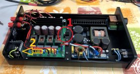
2. Make sure it's secure haha
It fixed with screws. We should use an hammer to move it. 😉
Stéphane
- Yes, remove tiny feedback caps.
- (optional) Change C11 to 10uF C0G 0805 or 0603
Version V1A modification:
Change C17 to 1uF 0805 C0G using instructions in my email.
Lester...I know the feedback cap removal works for both PFFB and non-PFFB boards. What about the C11 & C17 changes. Are those two changes based on having PFFB running on the board or will they benefit a non-PFFB implementation as well?
I guess you’re now calling the original version of your amp "V1A”?
Thanks, Pete
Hi Lester.
I've a problem with mods.
When the Topping D50s DAC switch on/off (not switching off/on music stream, or pause), I got big ploc now in the speakers.
Last changes where PFFB AND Silmic caps before amp-ops.
Stéphane
I've a problem with mods.
When the Topping D50s DAC switch on/off (not switching off/on music stream, or pause), I got big ploc now in the speakers.
Last changes where PFFB AND Silmic caps before amp-ops.
Stéphane
Last edited:
D
Deleted member 148505
Lester...I know the feedback cap removal works for both PFFB and non-PFFB boards. What about the C11 & C17 changes. Are those two changes based on having PFFB running on the board or will they benefit a non-PFFB implementation as well?
I guess you’re now calling the original version of your amp "V1A”?
Thanks, Pete
1st 10 modules is "V1" with white LEDs.
2nd 10 modules is "V1A" with green LEDs and some PCB layout change.
V1B, V1C and so on...
The split supply module that I will release on February will have a new name to differentiate it from single supply version.
What's the value of the capacitors? The caps near TPA3255 should be 10uF.Hi Lester.
I've a problem with mods.
When the Topping D50s DAC switch on/off (not switching off/on music stream, or pause), I got big ploc now in the speakers.
Last changes where PFFB AND Silmic caps before amp-ops.
Stéphane
Can you put back the 22uF Muse UES BP Green Caps in CA1, CA2, CB1, CB2?
Please reverse the connection of CA1, CA2, CB1, CB2.
The "BP" label on caps should be put on + label on the PCB. (positive should be pointing at the opamp since it has a higher VMID)
Regards,
Lester
What's the value of the capacitors? The caps near TPA3255 should be 10uF.
You're talking C1, C2, C3 and C4?
They're now 22uF Silmic (was Muse BP 22uF).
I'll put back the 22uF Muse before opamp.
Stéphane
In any case, you are supposed to off the power amp 1st. Powering down the dac while the power amp is on will result in the pop.Hi Lester.
I've a problem with mods.
When the Topping D50s DAC switch on/off (not switching off/on music stream, or pause), I got big ploc now in the speakers.
Last changes where PFFB AND Silmic caps before amp-ops.
Stéphane
Lester: No more pop with Muse BP before op-amps. THANKS!
Beware others people. With Silmic II at this place: big pop at on/off of DAC.
Commstech: was not doing that before this mod and should not do that.
EDIT: and the sound is better using Muse BP before op-amps than Silmic...
Beware others people. With Silmic II at this place: big pop at on/off of DAC.
Commstech: was not doing that before this mod and should not do that.
EDIT: and the sound is better using Muse BP before op-amps than Silmic...
Last edited:
Did the op amp bypass cap removal. Went well. I did remove C1 to C4 to help gain access and then they were a little tricky to re install.
Haven't done the C17 mod yet....building up the courage! I recently soldered NDK SDA clocks...I thought they were small....these are TINY! Can I just move existing C17 along one 'pitch' or does desoldering render them less effective.?
I will be using big old school psu ....500va toroid etc...but I may try my LT4320 based rectifiers.
Looking forward to the comparison to my 3e amp.
Last edited:
D
Deleted member 148505
You need to remove existing C17, then use 0805 so that you will be handling a bigger cap.
The key is using flux and temp controlled iron. Using a very hot iron will melt all connections. If you use correct temp, you can solder individual joints one at a time.
Regards,
Lester
The key is using flux and temp controlled iron. Using a very hot iron will melt all connections. If you use correct temp, you can solder individual joints one at a time.
Regards,
Lester
I can probably re use C17 cap. I have the confidence to try. But maybe the soldering/ resoldering would fry it?
D
Deleted member 148505
I can probably re use C17 cap. I have the confidence to try. But maybe the soldering/ resoldering would fry it?
I already tried, they are very brittle, the metal part of it can easily come off of its body so you only got 1 or 2 shots to solder it.
Lester: No more pop with Muse BP before op-amps. THANKS!
Beware others people. With Silmic II at this place: big pop at on/off of DAC.
Commstech: was not doing that before this mod and should not do that.
Agree with Commstech,
Amplifiers should be turned on Last and turned off First. Transient spikes from turning other components on/off while the power amp is on can damage components. This should be non-negotiable regardless of what capacitor is installed 😉
AVDD
Hello JLester
What will be the value of C11 AVDD in the new production.
Best regards
Roger
Hello JLester
What will be the value of C11 AVDD in the new production.
Best regards
Roger
D
Deleted member 148505
Still the same, but I put a tap under the board so that an electro cap can be added. I will receive the boards next weekend.Hello JLester
What will be the value of C11 AVDD in the new production.
Best regards
Roger
Struggling ti find 0805 C0G 1uf...any links or part numbers please?
Thanks
Hi, sorry C0G is nonexistent for that value
 just use X7R 1uF to 10uF 0805 for that part.
C11 AVDD
" I put a tap under the board so that an electro cap can be added"
Thanks, this is a good solution
Roger
" I put a tap under the board so that an electro cap can be added"
Thanks, this is a good solution
Roger
- Status
- Not open for further replies.
- Home
- Vendor's Bazaar
- Amplifier Modules and PCBs For Sale