I have an 80s guitar amp that I want to use as a doner for a fresh build. Basically the poweramp is a sealed unit and makes unpleasant distorted noises and the preamp is a little worse. The chassis, cab, speaker and reverb tank are all in good order.
And there's a power supply, obviously.
I was hoping to drop a simple chipamp in the place of the current power amp, and then front it with a nice preamp circuit, but the power supply is a lot beefier than I expected. It's labelled primary 22a 34v but my mains voltage is 240v, so I'm reading +-70v dc after the rectifier.
I've used an LM3886 in a project before, but the datasheet is quite clear that this voltage will melt it. Should I just swap the transformer, or is there a suitable chip I can throw in here?
Use an IRS2092 based Class D amp. They are quite inexpensive and can handle whatever voltage the drivers are designed for. Sounds like you are looking for 300w class amp.
For example:
US $47.80 | IRS2092 High Power 2×600W/4ohm 2×300W/8ohm Class D HiFi Stereo amplifier Board Assembled B7-007 dual DC Power Supply Voltage
IRS2092 High Power 2x600W/4ohm 2x300W/8ohm Class D HiFi Stereo amplifier Board Assembled B7 007 dual DC Power Supply Voltage|Operational Amplifier Chips| - AliExpress
xrk971's proposal is best I can think of. I know of no single-chip class AB power amplifier handling +/-70V. TDA7293 can do as absolute max. +/-50V.
1) WHICH Guitar amp has +/- 70V rails? 😱I have an 80s guitar amp that ....... but the power supply is a lot beefier than I expected. It's labelled primary 22a 34v but my mains voltage is 240v, so I'm reading +-70v dc after the rectifier.
Specially in the 80s
Today we have Randall Warhead and a couple more, including my own DB7, but ... in the 80´s? MOST unusual.
Could only think a Lab Series amp, but they were in their own separate class.
2) what does this mean?:
primary 22a 34v 😕
3) search in this Forum for APEX amps, one which stands +/-70V rails or more.
Well designed and very practical amps, plus many built them, so you can ask for guidance.
Last edited:
The guitar amp didn't have +/- 70V rails, he already said it is marked 34V but he is using it on 240VAC to get +/- 70V, a no-no.
LM49810/30 will take +/- 100 Volts.
But I would prefer a new transformer, as the rest of the power supply will be designed for lower voltages. That will be dangerous if you run it at about double its intended voltage, especially on load.
And your problems might be because you are feeding it 220 volts. instead of 110 <?> which it was designed for.
At a lower voltage, you can choose a lot of chip amps, LM 1875 will take 64 volts max. 3886 is well regarded, and so on.
If the pre amp is a 4558, change to 5532, 2134, TL 072, whatever. You may have to set the gain and output levels. Again, I would put a socket, to try different chips, and input and output I would put pots during setup, replacing with fixed resistors after listening tests.
Here the transformer can be expensive, a large part of the total cost. The other choice would be to buy a step down transformer for the mains, again expensive.
Using the rest of it basically means chassis, cabinet, speaker and reverb tank...
Then it becomes a decision based on cost, nostalgia, salvage, the amount of time you can spend and so on...
But I would not run it on a voltage higher than intended. It would last for a rew hours or forever, but the rest of the circuit is going to be affected or damaged by the higher voltage.
If there are skilled people in the area, the transformer can be rewound to suit 220 volts, but here it will cost a lot...
Decisions, decisions...
A picture with a measuring scale/tape/pencil or whatever next to it would be nice.
The object next to it would help judge the size of the unit, as 22 amps * 34 Volts is 748 Watts, so the output is quite large.
Or it could be 220 / 34 volts which is a specially made one.
Also see the main power supply caps and their ratings, that too will give some idea of the intended working voltage.
Diodes will also be beefy for 22 Amps, I would expect ones with at least 30 amp ratings. But most are good to 600 volts, so not much help there.
Another reason for noise could be age related issues like bad contacts, corrosion everywhere, dry joints etc.
But first feed it the rated voltage after a thorough cleaning and inspection, you might find something obvious
Last edited:
Thank you for all the replies and excellent suggestions. The amp is a British made guitar amp, an Alligator 75, which by all accounts was not all that great to begin with. I, too, was astonished at the huge amount of power it was using... There is no way these amps were exported, they were not successful enough. It was definitely sold for UK use.
I'm concerned that I have measured incorrectly, or made rash assumptions, so I will post pictures of my DMM readings too.
The original poweramp was an hy364p. Which the datasheet lists as +-42v max, and 180w. I'm pretty sure the speaker is 100w max.
Regarding the rectifier, when I was looking last night I couldn't find it because it was tucked away under an output jack. I'll have to remove both to see any markings on it.
Honestly, the whole amp looks like it was thrown together in a rush, by hand.
Something doesn't add up! I'll post pictures tonight as I'm now off to work. Thank you again for taking the time to help me out.
Okay, I have definitely made some poor assumptions and simply not looked at the transformer hard enough.
I really appreciate how patient and kind you have all been here. I was tired and out of my depth when I posted, and this discussion has really helped me slow down and look at things methodically.
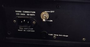
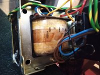
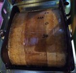
The mains side is clearly marked 120 - 0 - 120 - 0
and the other side is marked 34 - 0 - 34 and 2.2a
Besides the rest of my nonsense, I'm most embarrassed about missing the decimal point.
There are two capacitors, both rated 63v 4700uf. They both look healthy. I guess that should have been my first prompt to realise my error - thank you NareshBrd.
The bridge rectifier is labelled KBPC808, which I have Googled and should be 800v 8A.
I'm not going to power it up now as my children are around, and I'll need someone to hold the camera. I'll wait until the kids are asleep and measure voltage again. I expect to find that I've actually got +-35v DC.
Here are some pictures that will hopefully redeem my noob behaviour.
I really appreciate how patient and kind you have all been here. I was tired and out of my depth when I posted, and this discussion has really helped me slow down and look at things methodically.
The mains side is clearly marked 120 - 0 - 120 - 0
and the other side is marked 34 - 0 - 34 and 2.2a
Besides the rest of my nonsense, I'm most embarrassed about missing the decimal point.
There are two capacitors, both rated 63v 4700uf. They both look healthy. I guess that should have been my first prompt to realise my error - thank you NareshBrd.
The bridge rectifier is labelled KBPC808, which I have Googled and should be 800v 8A.
I'm not going to power it up now as my children are around, and I'll need someone to hold the camera. I'll wait until the kids are asleep and measure voltage again. I expect to find that I've actually got +-35v DC.
Here are some pictures that will hopefully redeem my noob behaviour.
Attachments
Use an IRS2092 based Class D amp. They are quite inexpensive and can handle whatever voltage the drivers are designed for. Sounds like you are looking for 300w class amp.
For example:
US $47.80 | IRS2092 High Power 2×600W/4ohm 2×300W/8ohm Class D HiFi Stereo amplifier Board Assembled B7-007 dual DC Power Supply Voltage
IRS2092 High Power 2x600W/4ohm 2x300W/8ohm Class D HiFi Stereo amplifier Board Assembled B7 007 dual DC Power Supply Voltage|Operational Amplifier Chips| - AliExpress
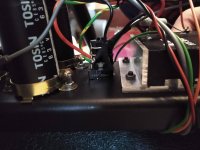
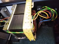
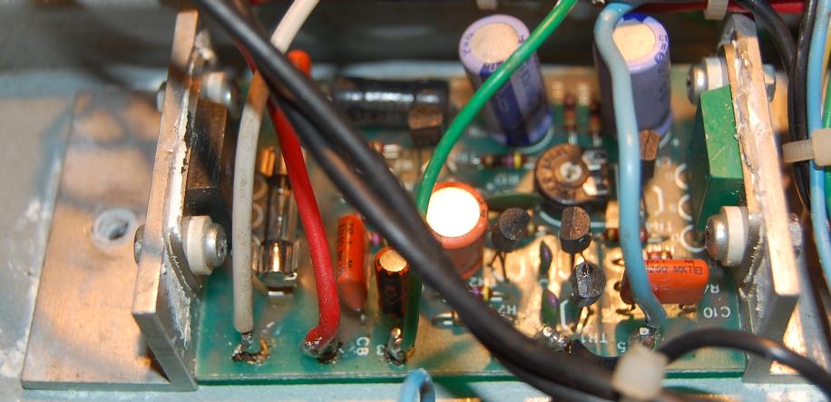
The heatsink is mounted 90 degrees wrong...
Okay, this is more like expected.
Have not seen Toshin capacitors here, but changing old capacitors seems to help. Use Nichicon, Elna, Panasonic, Wilna, Sprague, Rubycon, Vishay, or any well regarded brand.
Use a cheap washing detergent to clean the board, and an old toothbrush if really mucky, rinse the soap off properly, let it dry out. I leave PC supplies in the shade in warm rooms for a day or two, after rinse I use a blower to blow off excess water.
And after you are finished servicing and the unit works, put insulating varnish on the solder side of the board as insurance.
I have also used varnish in magnetic chokes and transformers which developed hum, I put it when they are warm, the varnish goes in and the noise reduces dramatically.
It is cheap compared to a burnt transformer.
Spike Milligan said his shoes went glug glug when he shined them up...like that it will seem if there is a gap in the insulation, if some talc filled epoxy or similar has been used. The varnish will go in and some bubbles will come out, and slowly the hum will stop as the gaps are closed.
Now you are well within the voltage range for a chip amp, and there are many people on this forum who will guide you how to go ahead.
Enjoy.
Last edited:
....The mains side is clearly marked 120 - 0 - 120 - 0
and the other side is marked 34 - 0 - 34 and 2.2a
I expect to find that I've actually got +-35v DC.
Do you understand why 34VAC to a diode and a cap is likely to be 48V DC, not 35V?
(Without cap it may be 30.6V "DC".)
...because the bridge rectifier multiplies the transformer output by a factor of 1.41, give or take mains variation? I *knew* that, but only because I've read it, and I definitely needed reminding.
I do not understand why the voltage would be lower without the capacitors. If you have time to explain, I'd love to learn!
You will either laugh or groan at this, but I went to test again and noticed that the battery on my DMM is low. It just confidently informed me that a AAA battery is putting out 2.5 volts.
I'm going to have a quiet word with myself while I order a new 9volt - if you want to keep this thread open long enough to indelicately roast me, please feel free.
Lessons learned? Look after your equipment, look at parts closely; if the maths doesn't agree, something is wrong; and that the most suspect component in all of this is me!
Buy a 9 volt alkaline
They last longer. The voltage is stable for a longer time compared to carbon zinc, but less than lithium.
If you want to do something really way out of left field, put 3 lithium batteries in series for 9 volts, use holders from scrap PCs or whatever.
The won't last as long as 9 volt cells, but lithium cells stay at 2.96 till they ae almost dead.
The battery voltage is used as a reference by the chip, but why they cannot put a zener or 7805 I cannot understand.
Beware of cheapo Chinese meters, and if you are an occasional user, buy a simple analog meter, there the battery is used only for resistance. So less issue like this one.
Duracell AAA lasted less than Ray-O-Vac but more than Panasonic.
Last edited:
I do not understand why the voltage would be lower without the capacitors. If you have time to explain, I'd love to learn!
When the capacitors are connected you get root(2) x V(AC) - the peak value of the AC (- a diode drop). When there are no capacitors, the meter will be reading the rms value of the sine wave from the transformer, or just V(AC).
So with no capacitors connected, the meter reading should be ~71% of the value when the caps are connected. The voltage printed on the transformer is the AC value.
Last edited:
Focusing on the actual amp (Forumites tend to digress 😉 )
1) it´s not a so-so amp but a killer SS one.
Of course anything SS will be *despised* compared to anything having any orange glow glass bottle inside ... even if said glow comes from a strategically placed orange LED 🙂 , and doubly so if "nobody famous" used it
I searched a little, plus your pictures, and it definitely looks like an unrecognized Sesionette 75 brother, same quality and type of construction
1) same HY*** MosFet power amp. Very high quality amplifier, very popular in the early 80s
Sadly unavailable for decades now, Sessionette used to offer a drop-in bipolar replacement module, not sealed but conventional open PCB plus thick L shaped aluminum angle to mount it to heatsink (which is the thickish aluminum back panel).
Try to get one, or you can adapt a similar power amp module which fits in that space.
Take a look at:
Award Session Sessionette Amplifiers. Welcome to award-session.com [AwardSession Sessionette Amplifiers]
Shortest no problem solution would be:
Some people try to repair the original HY module or its aftermarket replacement but the job can become hairy neurosurgery:
and that IF you can get the proper parts.
Try to get a ready made 80-150W power module that fits instead, it must be comfortable with +/-48V rails.
Notes:
* do not start replacing caps *yet* , first repair/replace power amp, then go after other details.
* that is not a "misplaced heatsink" but the extruded aluminum case for the potted poweramp. The actual heatsink is the back panel.
* like Sessionette, it also sports a highest quality speaker.
Sessionette used the heaviest Celestion available (K85 or similar?) , yours a top of the line FANE speaker (used in best Hiwatt and Orange cabs).
1) it´s not a so-so amp but a killer SS one.
Of course anything SS will be *despised* compared to anything having any orange glow glass bottle inside ... even if said glow comes from a strategically placed orange LED 🙂 , and doubly so if "nobody famous" used it
I searched a little, plus your pictures, and it definitely looks like an unrecognized Sesionette 75 brother, same quality and type of construction
1) same HY*** MosFet power amp. Very high quality amplifier, very popular in the early 80s
Sadly unavailable for decades now, Sessionette used to offer a drop-in bipolar replacement module, not sealed but conventional open PCB plus thick L shaped aluminum angle to mount it to heatsink (which is the thickish aluminum back panel).
Try to get one, or you can adapt a similar power amp module which fits in that space.
Take a look at:
Award Session Sessionette Amplifiers. Welcome to award-session.com [AwardSession Sessionette Amplifiers]
Shortest no problem solution would be:
The early MkI models have an ILP 'black block' power amp module (HY200 or HY248) and should be avoided.
Earlier pre 'MkII Mosfet' Sessionette models will need a new power amp module @ £59.00
Some people try to repair the original HY module or its aftermarket replacement but the job can become hairy neurosurgery:
and that IF you can get the proper parts.
Try to get a ready made 80-150W power module that fits instead, it must be comfortable with +/-48V rails.
Notes:
* do not start replacing caps *yet* , first repair/replace power amp, then go after other details.
* that is not a "misplaced heatsink" but the extruded aluminum case for the potted poweramp. The actual heatsink is the back panel.
* like Sessionette, it also sports a highest quality speaker.
Sessionette used the heaviest Celestion available (K85 or similar?) , yours a top of the line FANE speaker (used in best Hiwatt and Orange cabs).
This thing looks like a suitcase with a big speaker and lots of knobs on top front above speaker?
There are articles about the company and the product, it did not sell in large quantities, and the company folded.
Maybe it was too expensive for its market, maybe not many buyers for guitar amps, whatever.
Bear in mind that it has been sitting for decades, a thorough clean and inspection will be worth it.
Look it up on guitar forums, and on forums about Toshin capacitors.
Capacitors do tend to corrode, more so if lying unused.
As for the next step, there are many people here with more experience than me.
They will tell you what chip to use, you need about 70 to 100 watts mono?
Last edited:
...because the bridge rectifier multiplies the transformer output by a factor of 1.41,...?...
Because AC power from far away is always delivered as "Sine".
If we heat a light bulb or toaster, we want to know the "equivalent in DC", because DC is simpler, and we want to know the Heating Effect. This is "RMS" and how utility AC is specified.
The rectifier-capacitor AC-to-DC converter is a "Peak Catcher". It want to charge-up to the peak of the incoming wave. For a Sine wave, this is 1.414 times the RMS value.
There are also choke-filtered rectifiers, and average-responding meters. The Average of a Sine is 0.9 times the RMS. With an old needle-meter, a "cap input" filter with capacitor left off would read 0.9 times what the marking on the transformer said. Modern clever-meters may come to other answers. But when say 300V of AC makes 273V of DC, we shout "put the cap on!" because that's a likely situation.
Average is less than RMS because heat rises faster than voltage, so the peaks count more.
Hmmmm.... Google tells me that the Peak is 1.000, RMS is 0.707. True, except utility power is not sold by Peak, transformers and lightbulbs are not rated Peak.
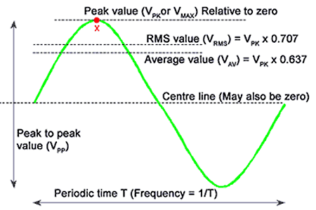
Do your math and you can figure the answers RELative to the way juice is sold and used.
Attachments
....The battery voltage is used as a reference by the chip, but why they cannot put a zener or 7805 I cannot understand....
I have not seen the battery used as a reference.
The battery feeds a reference device. Say a 7V Zener through a 2k resistor. 1mA diode current. But if the battery voltage falls too far, the diode current goes to zero and the reference voltage falls. Now any external voltage "looks large" compared to the shrunken reference voltage. At like 4V-5V from the "9V" it reports "AAA battery is 2.5 volts."
You should be seeing a LO BATT in the display. All these chips have it, though I suppose not all meter-makers implement it. Note where it is for the next time the battery fades away.
Last edited:
- Home
- Amplifiers
- Chip Amps
- Chipamp appropriate for +-70v