Hi all,
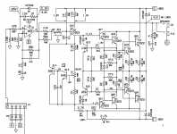
I have a GK800rb (schematic/service manual here, preamp board rev E, power amp and power supply board are rev C) which has obviously seen heavy use. It is currently damaged on the 300w side and I'm having trouble pinpointing the exact problem.
Symptoms:
- DBT (75w bulb, no load attached) glows as I turn up the mains with a variac
- DBT does NOT glow if I disconnect the +/- 85VDC wires from the power supply board (all power supply rails are correct)
- DBT also does not glow if I have the +/- 85VDC wires from the PS board connected and I disconnect the +/- 15VDC P2 header from the power amp board
What I've tried:
- Replaced the obviously burnt components on the power supply and power amp board (most of the output transistors and some of the A06/A56s, a few resistors)
- Rechecked the output transistors for shorts/opens
I would like to probe voltages on the 300W section, but I don't want to leave the amp powered up with a bright bulb. My next thought was to replace U1 (even though the 100W side of U1 seems to be ok). Is there a way to check this JFET in circuit? Any other tests I can do without powering up the 300W side?
Thanks for any and all help!
There´s no other way.I would like to probe voltages on the 300W section, but I don't want to leave the amp powered up with a bright bulb.
In any case the bright bulb means curremt and voltage ARE being limited.
Turn amp ON (through DBT of course) and measure voltages as needed.
Turn OFF only if something starts smoking or a transistor becomes VERY hot or a capacitor overheats quickly.
Use the "universal" rule:
1) Transistors must have the proper C-E polarity as in Positive for NPN and viceversa
2) Vbe must be again proper polarity and around 0.65 V
Any transistor not meeting both, needs close inspection.
Beware sometimes a transistor has, say, 5 or 6V OPPOSITE B-E polarity, that usually means that particular transistor is not bad itself, but DC feedback is desperately trying to make it compensate for *another* one which is the actual problem.
Measured the below results. No Variac (only DBT). Negative lead of DMM (set to VDC) on emitter. 75W bulb in DBT remained bright throughout entire test. No smoke at least 🙂 Sorry for the formatting; I couldn't figure out how to input a table properly.
Q (type) VBE VCE
Q8 (NPN) .5 22.8
Q10 (PNP) -.5 -22.8
Q12 (PNP) -.5 -23.1
Q17 (NPN) .5 24.0
Q18 (NPN) .5 24.5
Q19 (NPN) .6 24.5
Q20 (NPN) .6 24.5
Q21 (PNP) -.6 -23.1
Q22 (PNP) -.6 -24.1
Q23 (PNP) -.6 -23.7
Q24 (PNP) -.6 -24.0
Any of these readings look totally out of bounds?
Q (type) VBE VCE
Q8 (NPN) .5 22.8
Q10 (PNP) -.5 -22.8
Q12 (PNP) -.5 -23.1
Q17 (NPN) .5 24.0
Q18 (NPN) .5 24.5
Q19 (NPN) .6 24.5
Q20 (NPN) .6 24.5
Q21 (PNP) -.6 -23.1
Q22 (PNP) -.6 -24.1
Q23 (PNP) -.6 -23.7
Q24 (PNP) -.6 -24.0
Any of these readings look totally out of bounds?
I checked the +/- 15V rails with the header (from the power supply board to the power amp board) attached: I am seeing ~+13.7 VDC at pin 8 and ~-14.4 VDC at pin 4 of U1 (referenced to chassis ground). The voltages at the +/- 15 VDC header are around +/- 14.8 VDC with the header disconnected from the power amp board. Is there a way to check U1 in-circuit? Should I just replace it and see if that helps?
Swapped U1 with an LF353 (datasheet here) from a different amp; no change in behavior. I also measured the below voltages on the U1 pins (VDC, all referenced to chassis ground).
Pin 7 shouldn't be negative, right? Does this suggest the issue is downstream of U1? Any way I can pinpoint the problem component(s) without blindly swapping parts?
- -4
- 0
- 0
- -14
- 0
- 0
- -2.8
- 13.8
Pin 7 shouldn't be negative, right? Does this suggest the issue is downstream of U1? Any way I can pinpoint the problem component(s) without blindly swapping parts?
Adjusting the bias trimpot R38 significantly decreases the bulb brightness, so maybe it's just biased too hot?
I don't have a scope or a cab capable of handling 300 watts (mine is rated at 75W rms), it is still possible for me to check the bias correctly? Based on the procedure (attached), it seems like the master volume needs to be at 10 (although the volume knob is at 0).
I'm also not sure I understand the bias procedure, has anyone done this before? Can I use a frequency generator app on my phone to input a 200 Hz sine wave (at 5mVrms) at the input? What does it mean by "most negative/positive of the emitter resistors?
Attachments
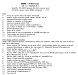
Bias must be NO signal. I would turn all knobs to zero. They want them up assuming you want to see something on the 'scope (step 1, steps 9-10); but bias is a no-signal calibration.
There's a bunch of 0.33 Ohm 10 Watt resistors. Meter one and find the trim, set for 3mV-4mV. Check the other 0.33 in that channel. Re-trim so the highest one reads 5mV and the others a few mV lower.
This sets each final transistor for almost 15mA idle current. This is on the cold side, G-K is leaving a heap of safety margin against thermal run-away.
Interesting update: I wasn't able to reduce the bias in the +85V section easily (reading still showed 15mVDC with R38 turned all the way). I removed R38 and checked with a multimeter; it measured ok. However, reinstalling R38 allowed me to lower the bias voltage to an acceptable level (and the DBT now does't glow at all!). Sooo, must've been a cold solder joint on R38?
The issue I have now is that if I bias Q18 and Q19 to have 5mVDC across the emitter resistors, I have ~.4mVDC across Q20. This is probably due to the fact that Q18 and Q19 are MJ15001s and Q20 is a MJ15022. Should I replace Q18 and Q19 (and Q17) with MJ15022s to match Q20 (and Q8)?
The issue I have now is that if I bias Q18 and Q19 to have 5mVDC across the emitter resistors, I have ~.4mVDC across Q20. This is probably due to the fact that Q18 and Q19 are MJ15001s and Q20 is a MJ15022. Should I replace Q18 and Q19 (and Q17) with MJ15022s to match Q20 (and Q8)?
Oh,didn´t see the thread for 2 days and you posted a lot. 🙂Ok, so I should power up through DBT and measure Vce and Vbe for all output transistors?
Fine, but let´s restart methodically.
My first question was:
Which starts withTurn amp ON (through DBT of course) and measure voltages as needed.
* +/- main rails (nominally +/-85V)
* in this particular amp: *power amp* +/-15V rails at power amp PCB
* DC volts at speaker out. Might find normal offset there (<100mV DC) or some hairy one.
* everything with: NO signal, NO load whatsoever , neither speaker nor load resistor.
After this, we go on with other voltages.
EDIT:
I assume you are referring to this particular version, on Page 17:
Attachments
Last edited:
Thanks JM, see my previous posts for power rail and output transformer readings (all look ok with 15V header disconnected from power amp board).
Current status is that the amp probably had a bad solder joint on R38. However, I still have the below question about output transistor matching (see post #14).
Unfortunately Mouser doesn't have any MJ15022s in stock, so is it ok to replace all the NPN output transistors with MJ15024s (and leave the PNPs as MJ15023s)?
Current status is that the amp probably had a bad solder joint on R38. However, I still have the below question about output transistor matching (see post #14).
The issue I have now is that if I bias Q18 and Q19 to have 5mVDC across the emitter resistors, I have ~.4mVDC across Q20. This is probably due to the fact that Q18 and Q19 are MJ15001s and Q20 is a MJ15022. Should I replace Q18 and Q19 (and Q17) with MJ15022s to match Q20 (and Q8)?
Unfortunately Mouser doesn't have any MJ15022s in stock, so is it ok to replace all the NPN output transistors with MJ15024s (and leave the PNPs as MJ15023s)?
Last edited:
Looks like I can get 10x MJ15022s for ~$25 shipped on eBay, so I'll do that and report back on biasing once I install the matched set.
They *might* be old non-RoHS inventory that someone is getting rid of if the photo is accurate. Might be fake. Photo might not be representative. Measure the base-emitter capacitance when you get them. They should be in the neighborhood of 6000-6500 pF. If they are, you might have dodged a bullet. Test with a dim bulb limiter for sure.
- Home
- Amplifiers
- Solid State
- Troubleshooting Gallien Krueger 800rb Bass Amp