Can anyone tell me how the anti-vibration circuit is configured on Rega's 24V motors. My understanding is that it is mostly a typical arrangement with a phasing capacitor, but there is also a trimmer to adjust the phase angle. Is this a variable resistor to adjust the voltage, or a variable capacitor to adjust the capacitance value and how is it supposed to be wired in respect to the coils?
I'm resurrecting an RP3 that fell victim to a PSU failure and the PCB sustained some damage, including a couple of missing traces and damaged markings on components. Any help greatly appreciated.
I'm resurrecting an RP3 that fell victim to a PSU failure and the PCB sustained some damage, including a couple of missing traces and damaged markings on components. Any help greatly appreciated.
Would it be possible to post pictures of the board? I am interested in seeing this circuit too. There is a video on youtube that shows the factory adjustment process where a PS is matched to each specific motor, but I think that this was for one of the upper-end turntables (Planar-8 perhaps?). The circuit board in the video looked a lot more complex than the one that comes with the standard 24V upgrade kit (Rega | 24 V Motor Upgrade Kit). I assume yours resembles the latter?
Normally you may have luck if you knew the manufacture of the motor and could access the spec sheet which would have the cap value. That may be difficult to do considering this is supposedly a custom Rega motor and not a commodity component.
Have you tried contacting Rega support? They may be helpful in this kind of situation.
If all else fails you could always purchase a 24V kit, get the component values and then return it. Yeah, that would be extremely cheesy. Slightly less cheesy would be finding a local Rega dealer and see if they have any kits in stock. If you ask nicely they may let you look inside the box.
Finally, if the circuit board sustained as much damage as you indicate, you may want to check the resistance of the two motor coils and make sure that the motor wasn't damaged as well. You may well end up having to purchase that 24V kit in any case. 🙁
One question - in the photo of the 24V kit, there are two inputs. The first is where the basic wall wart plugs in. The second appears to be some sort of multi-wire DIN plug and is where I assume that the alternative "Rega NEO PSU" can plug in. Does the DIN plug bypass the passive components on the board and go directly to the motor leads?
Good luck,
-b
Last edited:
Thanks for your response. Mine resembles the 24V upgrade kit. The multi-pin DIN connector is indeed for the TTPSU / Neo PSU. It doesn't wire to the motor leads; from what I can tell the Neo PSU and TTPSU provide a single-phase ace output and a 20V DC output. The 20V output is used to switch a relay on the motor PCB, which in turn switches to a second phasing cap and trimmer. Thus they achieve electronic speed control, and allow the phase to be adjusted independently for each of the two frequencies the power supply can generate and thus for each speed
The motor is a Premotec 31823. The Datasheet shows an 8UF cap but no detail on a possible anti-vibration trimming circuit. The Datasheet for the 31813 (110V) motor says that "trimmers can be added in series with each motor coil to electrically balance the motor", but that doesn't appear to be the case here as there is only one trimmer for for 33 and another for 45RPM operation.
I have checked the motor and it is perfect, thankfully. It looks like the board acted as a fuse.
Ahh, that explains it - you need the higher capacitance to run the motor at whatever speed is needed for 45 RPM records. Without the Neo PSU you'll just swap the belt on the pulley as normal.
The datasheet I found (https://docs.rs-online.com/8a9c/0900766b815922b7.pdf) recommended a 4.7uF for 50Hz operation, which would translate to about a 3.9uF for 60Hz (didn't know which side of the pond you are on). 8uF seems a little high based on some back of the envelope calculations.
Given that there is only that single adjustment, I suspect it is some sort of variable cap but that is just a guess. it could just as well be a cap with an adjustable resistance in parallel. Rega has used some novel circuits in the past for their motor drives.
Good luck,
-bill
I suppose it is very likely a trimmer cap. How much of a change in cap value would be required to have a significant difference in the phase angle, enough to cause a reduction or increase in vibration?
Have a feeling you are over-complicating, but I may be wrong.
Made a good deal on a NEO-TT-PSU so I recently installed a 24V motor to take advantage of it. Will post some pictures later. They should suffice for reverse engineering the REGA motor PCB.
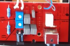
The board has two inputs, the standard AC input for the 50/60 Hz transformer that came with the deck. The other is similar to the old S-video/4-pin mini-DIN for the TT-PSU connections. NEVER CONNECT BOTH, the manual explicitly warn against this.
There is a relay, 2 resistors, 2 trim-pots and four capasitors on the PCB. One trimmer for 33RPM playing and the other for 45 RPM.
I may be wrong, but it was always assumed that the TT-PSU outputs sine waves of different frequencies depending if you are playing 33 or 45 records The NEO-TT-PSU allows fine tuning of motor speed with a resolution of 0.01RPM and changing between 45rpm and 33rpm by flick of a switch.
For turntables fitted with a 50Hz motor pulley; 50Hz for 33 RPM and 67.5 for 45 RPM. My assumption was always that two pins on the DIN connector is used when playing 33RPM records and the other two when playing 45. I further assumed that voltage on the "45-rpm" pins would activate the relay, selecting the "45rpm" trimmer.
Rega | Neo PSU – advanced turntable power supply
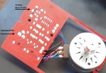
Anyway, you can find pictures of the controlboard here:
Rega 24v motor stopped working :-(- Vinyl Engine
Resolution may be a bit poor for reverese engineering.
I will check my old camera for pictures with better resolution and post tem here when I find them.
I will be curious to see circuit diagram and to see if my assumptions above hold true!
Made a good deal on a NEO-TT-PSU so I recently installed a 24V motor to take advantage of it. Will post some pictures later. They should suffice for reverse engineering the REGA motor PCB.
The board has two inputs, the standard AC input for the 50/60 Hz transformer that came with the deck. The other is similar to the old S-video/4-pin mini-DIN for the TT-PSU connections. NEVER CONNECT BOTH, the manual explicitly warn against this.
There is a relay, 2 resistors, 2 trim-pots and four capasitors on the PCB. One trimmer for 33RPM playing and the other for 45 RPM.
I may be wrong, but it was always assumed that the TT-PSU outputs sine waves of different frequencies depending if you are playing 33 or 45 records The NEO-TT-PSU allows fine tuning of motor speed with a resolution of 0.01RPM and changing between 45rpm and 33rpm by flick of a switch.
For turntables fitted with a 50Hz motor pulley; 50Hz for 33 RPM and 67.5 for 45 RPM. My assumption was always that two pins on the DIN connector is used when playing 33RPM records and the other two when playing 45. I further assumed that voltage on the "45-rpm" pins would activate the relay, selecting the "45rpm" trimmer.
Rega | Neo PSU – advanced turntable power supply
Anyway, you can find pictures of the controlboard here:
Rega 24v motor stopped working :-(- Vinyl Engine
Resolution may be a bit poor for reverese engineering.
I will check my old camera for pictures with better resolution and post tem here when I find them.
I will be curious to see circuit diagram and to see if my assumptions above hold true!
I should probably clarify what I wrote before. The TTPSU and the Neo PSU do vary the sine wave output between 33 and 45RPM. What they don't do is produce dual sine waves to independently drive each phase like some power supplies do, hence the fact that the motor still needs the phase capacitors. You are correct that the relay on the board switches between the capacitors / trimmer for 33 and 45.
The part I'm struggling with is finding the values of those parts and how exactly they're wired. Some photos of the PCB if you have them would be great, especially if the component markings are readable and the traces visible. My aim is to restore this to exactly how it was from the factory but in true DIY spirit I begrudge buying the PCB. It may also prove useful to those fitting a 24V motor to other decks who don't wish to buy a Rega kit.
The part I'm struggling with is finding the values of those parts and how exactly they're wired. Some photos of the PCB if you have them would be great, especially if the component markings are readable and the traces visible. My aim is to restore this to exactly how it was from the factory but in true DIY spirit I begrudge buying the PCB. It may also prove useful to those fitting a 24V motor to other decks who don't wish to buy a Rega kit.
The tt psu outputs a single ac voltage which is phase split by the cap under the deck. Its just a cleaner ac supply multiple sinewave generator. At least the one for my p5 was.
Indeed, looking at the pictures on my old camera it seems my assumptions were wrong. On the (Neo-)TT-PSU there is a single AC output on two pins of the mini-DIN connector, with frequency determined by selected RPM. The other two pins drive the relay that select either 45 or 33 RPM phase network on 24-volt motor PCB.
If my reverse engineering is correct, the networks generating the "missing" phase is a Bourns trimmer in series with a capacitor (actually 2 capacitors in parallel).
I have not been able to identify the values of the Bourns trimmers, see attached images for capacitor values.
If my reverse engineering is correct, the networks generating the "missing" phase is a Bourns trimmer in series with a capacitor (actually 2 capacitors in parallel).
I have not been able to identify the values of the Bourns trimmers, see attached images for capacitor values.
Attachments

Last edited:
Thank you for these images, a great help. So presumably the trimmers are resistive and thus adjust the voltage rather than the capacitance.
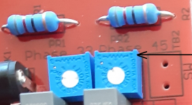
Most definitely trimmers are resistors, see attached picture.
Unfortunately no picture showing values of PR1 or PR2.
On that picture I also notice that the 45rpm pot on my PCB is maxed towards one end-stop. Almost as if the board was not trimmed for this speed.
R1 and R2 seem like 82 ohm.
On a side note: I measured W&F before and after the upgrade.
The 33 RPM improved, but 45 RPM was worse. Running 33RPM and instead moving belt on pulley as with traditional setups brought improvements on W&F.
For a DIY project with a good frequency controller for speed selection, it is worth investigating pros and cons of keeping the belt in 45 RPM position permanently, and instead reduce frequency for 33-RPM.
Attachments
Still haven't found definitive trimmer values for a 50Hz board so I'll likely replace the PCB but will reverse engineer the new one when it arrives.
I've recently been looking at the Rega 'upgrade' 24v motor and PCB which I bought to resurrect a Rega 25.
This worked out of the box, but I thought I'd make my own TTPSU equivalent. My first (incorrect) assumption was that the TTPSU input was for directly driving both phases of the motor, not using the phasing circuitry, however as you say this isn't the case and it has a single phase input, switching between the phasing circuits using a relay.
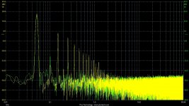
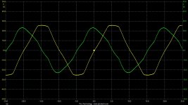
For reference, I looked at the two motor phases when using the standard set-up. The first picture is the voltage waveforms, where yellow = direct input, green = through phasing network. Pretty shonky for 'sinewaves' I thought! Spectrally, they can be seen in the second picture, lots of 3rd harmonic as expected.
So the first job was to modify the PCB to give direct access to the motor phases when using the mini-DIN input (actually a Kycon 4-pin power connector).
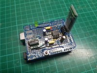
For the sinewaves, I thought I'd see what I could get using an Arduino Uno and filtered PWM, driving through a stereo amp with voltage rails sufficient to get to around the 25v peak (50v p-p) of the standard set-up.
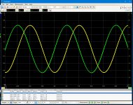
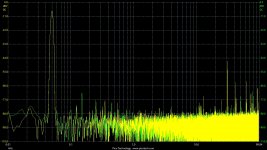
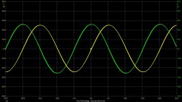
Using the default 510-cycle phase-correct PWM at 16MHz to give a frame rate of ~32us/31kHz, a 1024-point sinewave lookup table, and first-order low-pass filters with a cut-off at ~500Hz and gain of x0.275 to reduce the amplitude from 5v p-p to 1.375v p-p for the audio amp, gave the outputs shown in the third picture, with spectrum shown in the fourth. Pretty respectable looking sinewaves, with the dominant PWM-related tone at ~31kHz as expected. The output of the audio amp is pretty similar as shown in the fifth picture, but with additional attenuation of the 31kHz tone by setting the treble tone control to minimum (this has a cutoff at ~1kHz).
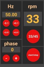
The sixth picture shows the prototype squeezed onto a shield. I'm using a bluetooth interface using the excellent RemoteXY control app to give a tuning interface for the 2 speeds, as shown in the seventh picture.
I'm pretty happy with the overall result, it drives the turntable motor well, with little noticable vibration using the 'finger-and-thumb' test.
Happy to share further details if this is of interest to anyone.
- Rich
This worked out of the box, but I thought I'd make my own TTPSU equivalent. My first (incorrect) assumption was that the TTPSU input was for directly driving both phases of the motor, not using the phasing circuitry, however as you say this isn't the case and it has a single phase input, switching between the phasing circuits using a relay.
For reference, I looked at the two motor phases when using the standard set-up. The first picture is the voltage waveforms, where yellow = direct input, green = through phasing network. Pretty shonky for 'sinewaves' I thought! Spectrally, they can be seen in the second picture, lots of 3rd harmonic as expected.
So the first job was to modify the PCB to give direct access to the motor phases when using the mini-DIN input (actually a Kycon 4-pin power connector).
For the sinewaves, I thought I'd see what I could get using an Arduino Uno and filtered PWM, driving through a stereo amp with voltage rails sufficient to get to around the 25v peak (50v p-p) of the standard set-up.
Using the default 510-cycle phase-correct PWM at 16MHz to give a frame rate of ~32us/31kHz, a 1024-point sinewave lookup table, and first-order low-pass filters with a cut-off at ~500Hz and gain of x0.275 to reduce the amplitude from 5v p-p to 1.375v p-p for the audio amp, gave the outputs shown in the third picture, with spectrum shown in the fourth. Pretty respectable looking sinewaves, with the dominant PWM-related tone at ~31kHz as expected. The output of the audio amp is pretty similar as shown in the fifth picture, but with additional attenuation of the 31kHz tone by setting the treble tone control to minimum (this has a cutoff at ~1kHz).
The sixth picture shows the prototype squeezed onto a shield. I'm using a bluetooth interface using the excellent RemoteXY control app to give a tuning interface for the 2 speeds, as shown in the seventh picture.
I'm pretty happy with the overall result, it drives the turntable motor well, with little noticable vibration using the 'finger-and-thumb' test.
Happy to share further details if this is of interest to anyone.
- Rich
Attachments
Can your motor speed control work with 110v @60 Hz? If it will, I'm interested in your circuit. I have the 24v motor upgrade already, the 33 rpm trimmer gets it close, I would prefer more accuracy.
Yes it's completely independant of the mains supply, the Arduino PWM generator/filter runs from a regulated 5v supply, then the amplifier to boost to 50v p-p can be any that works with your supply. My setup is for a UK 50Hz/24v motor so it generates 50Hz for 33rpm and 67.5Hz for 45rpm. If your motor requires 60Hz/81Hz then that can easily be changed in the firmware.Can your motor speed control work with 110v @60 Hz? If it will, I'm interested in your circuit. I have the 24v motor upgrade already, the 33 rpm trimmer gets it close, I would prefer more accuracy.
Then I am definitely interested in your circuit, this would be a great improvement over the wall wart supply.
Sure, I'll get the schematics drawn up, and post along with the Arduino code. (I've added in options for 50Hz or 60Hz when setting the defaults in the EEPROM).Then I am definitely interested in your circuit, this would be a great improvement over the wall wart supply.
As you have the Rega setup, I can also detail the mods to the PCB to allow direct access to the two motor phases if that would be useful?
- Rich
Have a little fiddle with the phase rich, exactly 90 degree might not perfect, it depends on how accurately the motor is made. Easiest way to check is to physically drive the motor and measure the sideways it outputs on the wires. Just rig it to the deck and spin the platter.
OK thanks for the tip, will give it a go.Have a little fiddle with the phase rich, exactly 90 degree might not perfect, it depends on how accurately the motor is made. Easiest way to check is to physically drive the motor and measure the sideways it outputs on the wires. Just rig it to the deck and spin the platter.
- Home
- Amplifiers
- Power Supplies
- Rega's 24V phase trimming circuit