View attachment 901859
Looks like a solder ball in here
Like poynton said, cleaning would help
Brian
That is what I saw. They are good photos but we know its not easy to inspect looking at a 2D image.
I would clean up anyway and take a magnifier to them for another inspect.
The transistor combinations should not be at fault, there are many images on the net showing most of the combinations of TO3 and TO220 devices used, the MJ15003 and MJ15033 being very common. I am sure I read that Quad use that combination in repairs. Likewise the low power tansistors, 560 and so forth.
Hi Everyone
First of all I measured the Zener voltages. I got +13.5v / -12.7v. I have the same voltages on the other healthy board.
Second R13 was out of specs. Replaced it
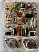
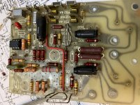
Thirdly I checked the welds, they are ok. No shorts or open. But the fact I flowed lots of Resin on the damaged areas gives an impression of shorted tracks. I am herewith attaching new pictures.
However now after replacing R13, I got a very weak sound with plenty of white noise.
First of all I measured the Zener voltages. I got +13.5v / -12.7v. I have the same voltages on the other healthy board.
Second R13 was out of specs. Replaced it
Thirdly I checked the welds, they are ok. No shorts or open. But the fact I flowed lots of Resin on the damaged areas gives an impression of shorted tracks. I am herewith attaching new pictures.
However now after replacing R13, I got a very weak sound with plenty of white noise.
Attachments
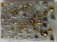


If I have a close look at the pics form #1, it appears to me that at least one diode D3 and/or D4 isn't in the same polarity in comparison between both boards.
Best regards!
Best regards!

Hi Assil,
Could I suggest that a good clean with Isopropyl or flux remover would help. It would make things a bit clearer and clean up any 'funnies'. An old toothbrush dipped in the stuff works wonders 🙂
Kind regards
Mike
Could I suggest that a good clean with Isopropyl or flux remover would help. It would make things a bit clearer and clean up any 'funnies'. An old toothbrush dipped in the stuff works wonders 🙂
Kind regards
Mike
R13 would have been a prime suspect and you say it was found to be faulty. You replaced and the symptoms have changed.
I just wonder if you are chasing a non existent fault now and that the problems are down to stability issues and the replacement semiconductors.
I just wonder if you are chasing a non existent fault now and that the problems are down to stability issues and the replacement semiconductors.
Hi everyone
Thanks for your support and pertinent observations.
My final understanding is that the tracks are so much repaired with links that this could be contributing to stability issues.
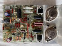
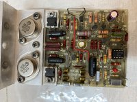
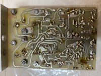
On account of same, I decided to rebuilt another spare board I had in my possession. I have replaced all transistors, electrolytic and diodes with new and replaced resistors where necessary.
I will test it tomorrow morning
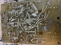
See attached photos. You will note that the pcb tracks are much better
Thanks for your support and pertinent observations.
My final understanding is that the tracks are so much repaired with links that this could be contributing to stability issues.
On account of same, I decided to rebuilt another spare board I had in my possession. I have replaced all transistors, electrolytic and diodes with new and replaced resistors where necessary.
I will test it tomorrow morning
See attached photos. You will note that the pcb tracks are much better
Attachments
Hi Mooly & everyone
The rebuilt was successful. Sounds good, stable with normal temperatures at heat sink. Thanks for all your support .
The lessons learnt is not to rebuilt Quads with heavily damaged pcb tracks.
I need one last advice on this set
(I) This set is fitted with a seperate clamp circuit. Is it worth rebuilding it ?
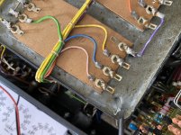
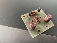
(II) The grey silicon fill in the transformer is semi molten. I don’t know why it became like this. See attached photo. Is there anything I can do about it ?
The rebuilt was successful. Sounds good, stable with normal temperatures at heat sink. Thanks for all your support .
The lessons learnt is not to rebuilt Quads with heavily damaged pcb tracks.
I need one last advice on this set
(I) This set is fitted with a seperate clamp circuit. Is it worth rebuilding it ?
(II) The grey silicon fill in the transformer is semi molten. I don’t know why it became like this. See attached photo. Is there anything I can do about it ?
Attachments
Pleased to hear that you have sorted it 🙂
The squidgy stuff in the transformer could/should be absolutely fine. I used to see a lot of that kind of thing in LOPTX's (line output transformers) and SMPS transformers in old TV's back when in the day. Just seems to be a very flexible and soft compound that they use.
The squidgy stuff in the transformer could/should be absolutely fine. I used to see a lot of that kind of thing in LOPTX's (line output transformers) and SMPS transformers in old TV's back when in the day. Just seems to be a very flexible and soft compound that they use.
The amp will burn your speakers out if it develops a fault
you can lose a 5 cent resistor ( feed to the opamp) and the unit will attempt to put 50 volts dc through your speaker
It happened a lot before the crowbar protection was fitted
I used to sell them back in the day safe amps are like safe sex use protection
Trev
you can lose a 5 cent resistor ( feed to the opamp) and the unit will attempt to put 50 volts dc through your speaker
It happened a lot before the crowbar protection was fitted
I used to sell them back in the day safe amps are like safe sex use protection
Trev
- Home
- Amplifiers
- Solid State
- Quad 405 - heavy distortion after Rebuilt