I determined that my first prototype Synergy-ish horn, constructed from PVC panels, suffered from a fatal Helmholtz resonance. So I built version 2--only to find a new issue. I haven't seen my solution reported before so I thought I'd share it in case it's useful to somebody. If you want to cut to the chase, the first set of measurements shows the problematic notch in the tweeter response, the second set shows the result of my fix, and the photos show the half-tubes that did the trick.
Long-winded background:
Version 1 of the horn was constructed with a focus on testing a molded adapter to match the compression driver to the main body of the horn, and integrating midrange taps without doing too much damage to the tweeter response. That all worked quite well, but when I pushed my luck and tried to add a pair of 8" woofers through slots in the horn, I found I hadn't thought far enough ahead.
First, I had to make an ugly and complicated assembly to provide surfaces to mount the woofer, and the result was that the woofers were so far from the inner surface of the horn, that that woofer slots and volume behind them formed very effective Helmholtz resonators tuned to about 600 Hz---right in the middle of the midrange's intended operating range. I filled some of the volume in front of the woofer cones but it just shifted the frequency up a bit; the notch still existed.
On to horn version #2:
I modified the horn dimensions so that the woofers fit more readily without complicated structures tacked on. I also made the volume between the woofer cones and the horn's walls much smaller. No more midrange Helmholtz notch! Success!
But when I started making more careful measurements, I discovered that if the mic were placed precisely on-axis---equidistant from all four woofer ports---a nasty notch appeared at a much higher frequency (~ 5 kHz). The notch depth dropped quickly off-axis, but it was too annoying to ignore, even if most listeners would likely not hear it.
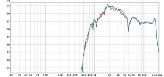
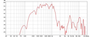
I tried over a dozen fixes, including acoustic foam in the woofer slots, porous covers of various sorts, half-covering the slots. Nothing really solved the problem except completely covering the slots with two layers of masking tape. I thought I might have simply moved the Helmholtz resonance much higher in frequency (although 600 Hz -> 5 kHz seemed hard to believe) so I removed the woofers behind the slots. Doing so made almost no difference in the notch (see the first set of measurements which show the tweeter response with and without woofers installed). So it clearly was not a Helmholtz resonance.
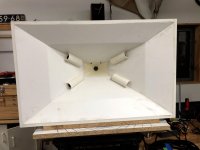
I was ready to quit on horn version 2 when I tried one last idea. I tested the idea with tape and the results were promising, so I made the more permanent version shown in the photos. My goal was to place thin shields in the form of half-tubes over the woofer slots. I wanted to orient the tubes so that the tweeter's output would pass along and through the tubes with minimal disturbance, but the scattering from the woofer ports would be blocked from interfering destructively on-axis. It works better than I anticipated.
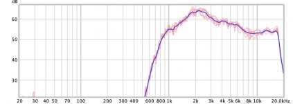
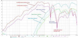
The second set of measurements shows the collection of raw tweeter measurements (no equalization) made over a range of 20 degrees horizontally and 20 degrees vertically. The bold line shows the vector average. They are acceptably consistent for my taste, and the nasty notch is gone. Equalizing that result will be a much easier task than dealing with the angle-sensitive notch.
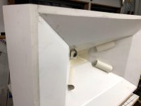
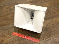
The first two photos show the half-tubes mounted over the woofer slots, with the second photo emphasizing the tweeter output's straight shot through the tubes. The third photo show one tube removed so the slot dimensions are clearer.
I made the half-tubes from thin PVC sheets sliced off a PVC board. I used a heat gun to make them flexible and then wrapped them around a pipe to achieve consistent dimensions.
No doubt somebody did this in 1947 (there seems to be nothing really new in acoustics) but it was a new trick for me so I thought I'd show the results.
By the way, I verified that the woofers' response is not adversely affected by the tubes, at least at the levels I tested. And the midrange seems not to notice the tubes either.
Few
Long-winded background:
Version 1 of the horn was constructed with a focus on testing a molded adapter to match the compression driver to the main body of the horn, and integrating midrange taps without doing too much damage to the tweeter response. That all worked quite well, but when I pushed my luck and tried to add a pair of 8" woofers through slots in the horn, I found I hadn't thought far enough ahead.
First, I had to make an ugly and complicated assembly to provide surfaces to mount the woofer, and the result was that the woofers were so far from the inner surface of the horn, that that woofer slots and volume behind them formed very effective Helmholtz resonators tuned to about 600 Hz---right in the middle of the midrange's intended operating range. I filled some of the volume in front of the woofer cones but it just shifted the frequency up a bit; the notch still existed.
On to horn version #2:
I modified the horn dimensions so that the woofers fit more readily without complicated structures tacked on. I also made the volume between the woofer cones and the horn's walls much smaller. No more midrange Helmholtz notch! Success!
But when I started making more careful measurements, I discovered that if the mic were placed precisely on-axis---equidistant from all four woofer ports---a nasty notch appeared at a much higher frequency (~ 5 kHz). The notch depth dropped quickly off-axis, but it was too annoying to ignore, even if most listeners would likely not hear it.
I tried over a dozen fixes, including acoustic foam in the woofer slots, porous covers of various sorts, half-covering the slots. Nothing really solved the problem except completely covering the slots with two layers of masking tape. I thought I might have simply moved the Helmholtz resonance much higher in frequency (although 600 Hz -> 5 kHz seemed hard to believe) so I removed the woofers behind the slots. Doing so made almost no difference in the notch (see the first set of measurements which show the tweeter response with and without woofers installed). So it clearly was not a Helmholtz resonance.
I was ready to quit on horn version 2 when I tried one last idea. I tested the idea with tape and the results were promising, so I made the more permanent version shown in the photos. My goal was to place thin shields in the form of half-tubes over the woofer slots. I wanted to orient the tubes so that the tweeter's output would pass along and through the tubes with minimal disturbance, but the scattering from the woofer ports would be blocked from interfering destructively on-axis. It works better than I anticipated.
The second set of measurements shows the collection of raw tweeter measurements (no equalization) made over a range of 20 degrees horizontally and 20 degrees vertically. The bold line shows the vector average. They are acceptably consistent for my taste, and the nasty notch is gone. Equalizing that result will be a much easier task than dealing with the angle-sensitive notch.
The first two photos show the half-tubes mounted over the woofer slots, with the second photo emphasizing the tweeter output's straight shot through the tubes. The third photo show one tube removed so the slot dimensions are clearer.
I made the half-tubes from thin PVC sheets sliced off a PVC board. I used a heat gun to make them flexible and then wrapped them around a pipe to achieve consistent dimensions.
No doubt somebody did this in 1947 (there seems to be nothing really new in acoustics) but it was a new trick for me so I thought I'd show the results.
By the way, I verified that the woofers' response is not adversely affected by the tubes, at least at the levels I tested. And the midrange seems not to notice the tubes either.
Few
Attachments

Last edited:

Well that's novel! Congrats on the innovation and the perseverance to get there. Sounds like it was a long a frustrating road with a clever payoff.
To me it doesn't look like it would work, but you've shown that it does.
To me it doesn't look like it would work, but you've shown that it does.
It certainly was not the first approach that came to mind! More of a last-ditch effort resulting from lying in bed trying to visualize what the wave front from the tweeter was doing. I was trying to introduce a structure that was "skinny" as viewed by the tweeter's propagating wave front but wide in the direction that blocks the path from the woofer slots that leads to the destructive interference. Tape was the first attempt, and the tubes in the photos are the second. I could try something fancier but if these get the job done I may glue them in place and move on.
I only have quick and dirty measurements on the woofer and midrange with the tubes in place, but as I mentioned, the tubes don't seem to be bothering the responses. I'll need to do a more thorough study when I return home (I'm on the road at the moment) to see if anything shows up off-axis. On-axis I don't see any obvious new features in the midrange response that were not there before the tubes were taped in place.
Few
For what it's worth, here is the single midrange measurement I made on-axis, at 1 m, in a highly reflective environment. The 257 Hz notch is from floor and ceiling reflections (I windowed this at 20 ms--the notch looks much worse without windowing). The notch just under 800 Hz may be the new position of the woofer + slot Helmholtz resonance but I haven't verified that. In any case, it was there before the tubes were installed.
The mids will be rolled off at 350 Hz and 1200 Hz with 4th or 6th order Linkwitz-Riley FIR filters so the ugliness outside that range is pretty well tamed.
Few
The mids will be rolled off at 350 Hz and 1200 Hz with 4th or 6th order Linkwitz-Riley FIR filters so the ugliness outside that range is pretty well tamed.
Few
Attachments
Very innovative !
I'm surprised at the depth of the notch in the tweeter, before the tubes were added.
Although I have to say I've seen some crazy measurements on my synergy builds when the mic is positioned precisely on axis.
I've measured, and witnessed the time of flight from the CD shorten up from direct flight timing slightly off axis. It appears the 4 walls sum CD reflections to form a virtual acoustic source closer to mic than the CD itself.
I guess the summed reflections are stronger than the direct OA CD output.....dunno for sure here though...
That phenomenon was measured with the CD on the horn before putting any ports in.
I like to benchmark the horn prior to adding ports, making the assumption it represents the best case response achievable after adding ports.
Oh before i forget to ask, do you short out driver sections that aren't being measured?
I've found sometimes this eliminates some otherwise unexplained notches, after adding ports and drivers. Shorting the CD has mattered too, when measuring mids.
I'm also surprised that tape over the ports provided enough blocking.
I've ended up using thin sheet steel over the ports when checking their effect. Maybe i just test at higher levels, since i measure outdoors and need to achieve an acceptable SNR...?
Again, very innovative...I might see if there a way to try such on one of my boxes! I had thought about trying triangular wing shaped flaps over the ports, but the idea of aimed, non interfering, tubes has never ever crossed my mind.
Thx for sharing 🙂
Thanks for your interest.
The tweeter notch reaches the depth I've shown only if I go out of my way to perfectly position the mic. Just a degree off axis reduces the depth noticeably.
I've found I need two or three layers of tape to fully block the slots but multiple layers usually does the trick if the tape is taut.
I usually have the unused drivers wired to the power amp outputs but I have to admit I haven't been super diligent about that. Thanks for the reminder.
If you happen to try the tubes, please report back. I'd be curious to know if they only work in my situation or if they have broader applicability.
Few
Very innovative solution!
It may be possible to cut existing PVC pipe along the axis to form the curved shields? That would be easier than reforming tubes from flats. Also, maybe the end profiles can be shaped to be angled and sharpened like the end of a magnified hypo needle. Or like a K-tube tweeter. Not sure if needed though.
It may be possible to cut existing PVC pipe along the axis to form the curved shields? That would be easier than reforming tubes from flats. Also, maybe the end profiles can be shaped to be angled and sharpened like the end of a magnified hypo needle. Or like a K-tube tweeter. Not sure if needed though.
It certainly was not the first approach that came to mind! More of a last-ditch effort resulting from lying in bed trying to visualize what the wave front from the tweeter was doing.
Would have thought this was the result of a long toilet session 😀
Very cool idea indeed! What would happen if you were to close the back?
Hmm, a vent by any other 'name' is still a vent, so would have tried critically damping it first using an impulse test to damp down its pipe upper harmonics.
GM
GM
I considered slicing a pvc pipe but the stuff I had on hand was thick walled. To cut it in half longitudinally and sharpen its edges would have taken more than the two minutes it took me to warm and form each half-tube. I already had something set up on my bandsaw so that making thin slices of pvc was very quick and easy. That said, I'm sure similar results could be achieved with a variety of approaches.
I'm sure there was subconscious toilet-supported thinking along the way. I find proximity to porcelain tends to improve my creativity. I think closing one end of the tube would undermine the clear path I was trying to provide for the tweeter's output. That's just my guess; I haven't tried the experiment.
I tried several materials with different densities and thicknesses to tame the notch. I worked in both the time and frequency domains. My best effort cut the depth of the tweeter notch in half, but killed the woofer output by 5-6 dB at the same time. More porous materials had a bit less effect on the woofer output but were less effective on the tweeter notch. In the end, no damping that I tried worked as well on the tweeter notch as did the half-tubes, and they seem to have zero effect on the woofer---which is why I thought I'd share my results.
Few
I also struggled with a deep notch on my RAAL tractrix synergy horn. I wonder if the rounded port covers might help. But my ports are close to the tweeter plane.
https://www.diyaudio.com/forums/att...n-source-horn-nano-trynergy-raal-photo-01-jpg
https://www.diyaudio.com/forums/att...n-source-horn-nano-trynergy-raal-photo-01-jpg
Attachments
Interesting. It's obviously a significantly different situation, but who knows? My fix was a bit of a shot in the dark so I basically have only one data point to extrapolate from. Of course from that one point I can extrapolate to pretty much anywhere!
I just used two layers of blue masking tape (blue because I was working with high frequencies 🙂) to test out the idea and even with that slapped together approach it was clear I was on to something. So it doesn't take much effort to do a rough test. I would just try to be sure the "tube" surfaces run parallel to the propagation direction of the high frequencies.
Few
In the end, no damping that I tried worked as well on the tweeter notch as did the half-tubes, and they seem to have zero effect on the woofer---which is why I thought I'd share my results.
Good to know, thanks! That said, to critically damp a vent requires a porous material to be tightly stretched across it, so material density is normally quite porous with its tightness primarily doing the damping. Of course there is some LF roll off, so may need to be accounted for in the speaker's alignment.
Gm
There's my cue to pop up and mention that cutting PVC or other pipe along the axis with a rotary blade (like a table saw) can be a good way to get a pipe driven through yourself. I'll save everyone from me telling my story of woe on that for the zillionth time. But suffice it to say that there can be a LOT of pressure released from the pipe walls when it cuts through, making it grab hard onto the blade which then happily drives the pipe out like a bullet. So think what you're doing before cutting.Very innovative solution!
It may be possible to cut existing PVC pipe along the axis to form the curved shields? That would be easier than reforming tubes from flats. Also, maybe the end profiles can be shaped to be angled and sharpened like the end of a magnified hypo needle. Or like a K-tube tweeter. Not sure if needed though.
---
that said, the pipes over the slots is an interesting approach. I spent a stupid amount of time trying to put cloth, perforated plastic, honeycomb sheet, tape, cotton over slots to make them acoustically go away. A little horn wall over the slot like thos pipes make is clever.
Last edited:
I was thinking a hack saw down a 4in section of 1in PVC should not be a problem but thanks for the safety reminder about using a table saw!
Scary stuff. My scariest DIY incident was applying 50v inadvertently to a 25v rated 470uF electrolytic cap. It blew up inches from my hand with paper wrapping shrapnel like an M80 firecracker. Now I always stand back 8ft or behind a safety wall when powering up something for the first time.
Scary stuff. My scariest DIY incident was applying 50v inadvertently to a 25v rated 470uF electrolytic cap. It blew up inches from my hand with paper wrapping shrapnel like an M80 firecracker. Now I always stand back 8ft or behind a safety wall when powering up something for the first time.
Safety Note: A variac or bulb tester are a part of standard safety practice when building electronic equipment. They allow power to be applied in a controlled manner so that proper circuit operation can be verified before applying the full supply.stand back 8ft or behind a safety wall when powering up something for the first time.
Thanks, Herr Dr. Waslo: I had similar concerns (based on personal experience) but didn't want to come across as professing there's only one correct approach. I had my own scary experience longitudinally slicing PVC pipe. Yikes! I won't soon forget it. There's a reason some folks use sliced PVC pipe sections as clamps! My bandsaw is my new bestest friend: Zero kickback!
GM: I spent several days working from the assumption that I needed to damp a resonance associated with the woofer slots, but experimental results just didn't support that explanation (much to my surprise). It seems it's really a scattering (diffraction) problem, so critically damping isn't really applicable. It took me awhile to come to that conclusion, but I didn't see any measurements that conflict with it. If I weren't so pleasantly surprised by the results, I'd be a bit irritated by my misdiagnosis.
Few
- Home
- Loudspeakers
- Multi-Way
- Synergy-ish horn: Fixing woofer slot influence on tweeter