Hello All,
Hope your all doing well in these troubled times. I have just joined this forum to try and get some help with my amp (Marantz PM66 SE). Sorry in advance for the long winded post.
After having stored my hifi in the attic (I know BIG MISTAKE, I won't even say "hindsight an amazing thing" as a little logical thought should have stopped me from storing it in such a varied temp environment) anyway... connected it up and it actually worked for a minute or two. Had music coming out of both speakers, however one side was very low regardless of volume level. I messed around with the speaker plugs and still no improvement. Eventually, it just muted....no sound at all 😳 . When switching the amp on I could hear a click but nowhere as pronounced(loud) as it should be. This is a hifi system that has more value to me then it's actual financial worth and as I'm stuck in lockdown I thought I'd have a go at fixing it myself. I've been reading up 🧐 on capacitors, transistors, resistors...etc I don't have a huge amount of money to throw at it but I will give it my best shot to bring it back to life. I am your below average self taught fixer-upper, I have a multimeter, soldering iron, and a hammer lol 🔨
So one day I decided to open the amp... there were no obvious signs of capacitor explosions, however one of the large capacitors was very slightly swollen from the top and both of these large capacitors had a resin of some sort around the base. The pcb (think this is the sound board), from underneath, showed signs of burn in certain spots but not under the large capacitors. I immediately thought the capacitors had leaked out from the base so proceeded to remove them from the board. Having removed one of the capacitors I realised that the resin was not the electrolyte from the capacitor, it was some sort of glue to hold the capacitor in place :facepalm:. Kind of panicked and soldered it back in place lol.
After inspecting the board I noticed that the solder connections holding the three pin small transistor (D1508) had come loose. Re-soldered these on both sides, reassembled the amp, switched the amp on and a few seconds later something started to smoke 🔥 quickly switched off 🥵 . Plucked up the courage to switch it back on and the fuse (T1.6A 250V) blew. Upon further inspection of the pcb board I noticed one of the metal oxide resistors was reading 255ohms when it should be 330ohms. I'm assuming this is what heated up and started to smoke (total guess).
This is where I am at, obviously I could do with some help and advice. I'm trying to learn as much as I can before switching the soldering iron on. Also I'm 100% certain the capacitors (ELNA 10000uF 56V) need replacing but have no idea where to buy them. Some UK ELNA stockiest don't have the 10000uF 56V, I have found an ELNA 10000uF 63V on aliexpress but I really want to try to buy from UK so any ideas where I might be able to get these capacitors from?
I read up and watched countless videos on testing transistors (mosfet) and capacitors, thinking of removing the three transistors and the large capacitors from both sides of the board for testing. I am struggling with the markings on transistors :
One is marked as follows : A1256N with a R under the A and 6C under the N
Another marked as : D1508 with 6C above the D
the third is marked as follows : C3182N with R under the C and 5L under the N
Taking the first one as an example ...Is this a A1256N transistor? All the literature I have read state there should be two letters before the digital code. Also what does the R and the 6C mean?
Once I have understood/identified the components I will remove them and test them. Can anyone give me some advice on how to test capacitors and the above transistors. Info on google is so contradictory..one person says do this yet another says do that 😵
Am I going about this correctly? is there anything else I should check before taking the board apart?
If you have got this far with my post then thank you for reading, if you can give me some advice (other then buy a new amp or pay someone to fix it) that would be much appreciated.
Thank you & stay safe
bass out
The two large power supply smoothing capacitors your referring to C801 & 802 if tested with an ESR meter will normally be within specification.
If you wish to replace them, you can fit a high-quality capacitors from a different vendor it does not have to ELNA.
You can install 63 Volt capacitors just verify the diameter and height before ordering.
Examples can be found here from Mouser
https://www.mouser.co.uk/Passive-Co...hr0?P=1z0wqs8Z1yx4avu&Keyword=10000UF&FS=True
It would be good if you can provide a photograph of the Amplifier board, so I can see the brown glue and if it is covering any components or links.
Often for this model of Amplifier the brown glue will be covering several resistors in the protection circuit.
The glue must be removed as its corrosive and conductive, a plastic scrapping tool can be used to prevent damage to the circuit.
Eye protection should also be used as flakes of dried glue can flick up and cause eye damage.
The resistors that are covered with glue will need to be replaced.
The reference number is printed on the circuit board and the service manual will detail the value.
When you resoldered the voltage Amplifier transistor mounted on the heat sink, did you gain access to the solder side of the board via the bottom service panel, or did you remove the back panel and the Amplifier board from the chassis?
If you did remove the back panel and the Amplifier board fixing screws, they must be refitted prior to testing.
There is a common ground connection made via the Amplifier board and the chassis and the back panel.
The speaker terminal fixing screws when fitted connect to the Amplifier board ground.
Failure to fit them will result in damage to the Amplifier if powered up.
The issue you found with the voltage driver transistor having dry joints is quite common and is a major cause of failure.
All the dry solder joints on the Amplifier board should be reflowed, you will find them on all the transistors mounted on the Heat sinks and where there is discolouration on the board due to heat.
Those components will also need to be re-soldered.
It would also be good practice to replace the speaker protection relay as the contacts will be worn and oxidised specifications are 24 V DC coil DP/CO.
You will also find dry solder joints on the input RCA sockets on all the boards and the front tone board.
The headphone socket and balance control will need re-soldering.
The failure of the fuse will most certainly be due to the failure of the output transistors.
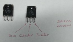
A1256N is a 2SA1256N and C3182N is a 2SC3182N
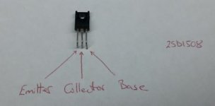
D1508 is a 2SD1508
The letters etc are date codes and of no importance.
What is critical is where you purchase replacement devices.
They must be soured from a reputable component supplier and be genuine originals.
Dönberg Electronics - Electronic Components and Equipment - UK (GBP)
Sadly, the marketplace is flooded with counterfeit Chinese copies that will not work as designed and often will fail after a short period of time or when powering up the Amplifier after repair.
The metal oxide resistor your referring to would not have gone low in value, you need to de-solder one end of the resistor or remove it then remeasure it.
When a resistor is in circuit the value may read lower due to the resistance of other components in the circuit.
If you look at the circuit board you will most likely see which component started smoking most likely a resistor near the failed output transistors.
You will need to test the components in the failed channel output and driver stage.
A component may look okay no visual sign of damage, but it may still have failed and only testing it will confirm this.
When output transistors fail there is a high possibility that the Emitter resistors have also failed.
The resistors are the white 3-legged ceramic resistor mounted vertically off the board.
There is some work required to fix this Amplifier and you will need to be familiar with reading circuit diagrams?
Also, normally a dim bulb tester would be used to prevent the Amplifier from drawing excess current during testing if there was still an issue.
Testing with out such a device could result in the failure of costly components that you have just replaced.
To test capacitors as advised an ESR meter should be used or at least a multimeter with a capacitance range exceeding the maximum value of capacitor you want to test.
Note Also large capacitors hold charge so they should be discharged prior to testing.
The testing of Transistors at a basic level can be done with a multimeter on diode test mode.
In this case if any of the output transistors read a short circuit or very low resistance between any of the legs then it needs to be replaced.
WOW! thank you Audio Service.
I ordered a few tools so I can unsolder/resolder as neatly as possible. When they arrive I will commence the operation. I will definitely upload pictures and try to work through your procedure.
One point I failed to mention in my original post, which you have picked up on, is regarding the screws holding the board to the chassis. I did remove the PCB from the chassis and upon first testing I did not screw the board down correctly which is why it started to smoke. ( I assumed this when it happened and you just confirmed it with your post ) I may have done more damage! 😱
I have been trying to source the caps as one of them is 100% faulty(unless you think otherwise) it's not reading any resistance at the terminals. Getting ELNA caps will be tricky because I spent most of today trying to source these from the UK but failed. I did find some on ebay and aliexpress BUT not a big fan of these sites. Based on what I have read the ELNA caps are quite good so was hoping to use them. In the event ELNA are a no-go, are you aware of any capacitor brands which are of equal, if not better quality, and readily available in the UK?
The transistors are still in circuit so can't test, once tools are delivered I will investigate.
The three legged resistor looks easy enough.
Anyway, will keep you posted (and anyone else who is interested) thanks again for the reply
bass out
Regarding the OP mentioning that they incorrectly replaced the PC board resulting in smoke/failure....
This now unfortunatly changes any reasonable "over the internet" suggestions on repairs.
It complicates things.
My suggestion would now be to take the unit to a professional servicer, and tell them about this additional issue/damage.....
Or continue this thread endlessly with speculation.
This now unfortunatly changes any reasonable "over the internet" suggestions on repairs.
It complicates things.
My suggestion would now be to take the unit to a professional servicer, and tell them about this additional issue/damage.....
Or continue this thread endlessly with speculation.
As advised the Amplifier board must be screwed to the chassis and the rear back panel fitted the screws for the speaker terminals must be fitted as they complete the common ground connection.
Fitting the Amplifier board screws alone will not sufficient.
The problem with the Auction web sites is there are counterfeit capacitors for sale.
If you refer to the link I provided for mouser it shows all the 10000uf capacitors for sale all are of good quality.
The only way to properly test a capacitor is with an ESR meter.
Regarding the OP mentioning that they incorrectly replaced the PC board resulting in smoke/failure....
This now unfortunatly changes any reasonable "over the internet" suggestions on repairs.
It complicates things.
My suggestion would now be to take the unit to a professional servicer, and tell them about this additional issue/damage.....
Or continue this thread endlessly with speculation.
Hello wiseoldtech, I understand your concern, but I will still be giving it my best shot from whatever help I can get. All help and advice is most welcome and gratefully received. Me personally I have nothing else to do, TV is as entertaining as watching paint dry, can't go out as people not following rules, not working because of covid...the only thing between me and going mad is this Marantz PM66SE

Take care and stay safe
Bass out
As advised the Amplifier board must be screwed to the chassis and the rear back panel fitted the screws for the speaker terminals must be fitted as they complete the common ground connection.
Fitting the Amplifier board screws alone will not sufficient.
The problem with the Auction web sites is there are counterfeit capacitors for sale.
If you refer to the link I provided for mouser it shows all the 10000uf capacitors for sale all are of good quality.
The only way to properly test a capacitor is with an ESR meter.
Hello Audio Service,
How are you? I hope all is well.
I have not made any advances on the diagnoses side (will be doing some tomorrow), however I thought I would upload some pictures to help explain the extent of the issue(s).
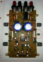
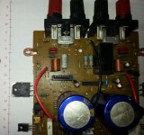
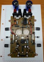
The below pictures shows the PCB, the red circles are where the board, from underneath, is discolored. You might be able to see that the capacitor on the left has a very slight bow on top.
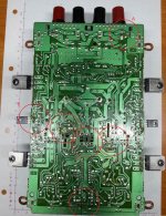
The below picture shows the corresponding underside of the board:
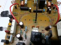
The next few pictures show the deposit (glue) holding the large capacitors in place. This is what I mistakenly thought was the electrolyte from the capacitors.
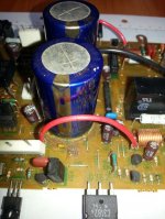
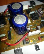
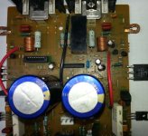
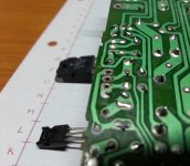
And finally a few more of the discoloration on the copper track side:
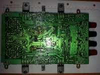

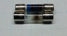
I read that it's possible to deduce some important points from what the blown fuse looks like 😕 I can't see it myself
You might be able to see my very poor attempt on soldering the capacitors....this is why I must wait for the right tools to do this properly

Bass out
Thank you for the Photographs, to remove the brown glue de-solder the large smoothing capacitors, any resistors that are covered in the glue need to be replaced.
The brown marks on the board are of no concern, it has only discoloured over time because the components are dissipating power hence the heat.
The blackened fuses show there is a short circuit which will be the output transistors you need to check each side.
I see the heat sinks are no longer attached, be aware the exposed metal on the back of the output transistors is not isolated.
What looks like white paper on the heat sink is actually a thermal transfer isolation strip called Mica.
You need to ensure that the output transistors are still isolated when you screw them back to the heat sinks.
If any area is ripped and metal is exposed you will need to fit additional Mica washers.
Also you can remove the flux after soldering by using flux remover or isopropyl alcohol.
Also you can remove the flux after soldering by using flux remover or isopropyl alcohol.
Flux, resulting from quality solder, isn't any worry.
It's not corrosive, it's not conductive, it's inert.
It may be unsightly, yet it's harmless.
However, many people, and the internet self-proclaimed (obsessed perfectionists) guru's, have created the myth/law that it must be removed.
Us pro techs think that's funny.
The removal of the flux for this repair has been advised because it is covering the multi pin connector from the volume control board making it difficult to see the quality of the solder joints.
OK so here goes 🙂
I started to take the transistors and capacitors off the board. I am writing this so that readers at the same electronics level as me , might be able to get a pointer or two.
As a beginner, de-soldering is not as easy as it looks. I was expecting the de-soldering pump to suck the molten solder from a few millimetres away...NOPE not the case the nozzle of the de-soldering pump has to be ON the joint. After removing the component a quick wipe with some de-soldering wick is very useful, as it will clean any remaining solder, final stage is to wipe the board with cleaning alcohol.
Below is a picture showing the transistors and capacitors removed from the board:
The extent of the glue holding the capacitors down can now be clearly seen:
Using the wick helped remove most of the old solder, but I might give it another pass just before re-soldering.
The glue was easily removed. I don't think it was conductive, had more of a rubbery texture, so it pealed of like pva glue.
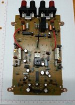
Now with the transistors off I looked at the data sheets I found on google and concluded that all the transistors were NPN with the following pin designation:
I followed the instructions I got from an online video to try and determine if the transistors were good or bad. In the picture below something like "+ ON B" means the positive terminal is on the base pin, so "- ON E" is negative terminal on emitter pin...etc
Transistors 1&2 are 2SC3182N
Transistors 3&4 are 2SA1265N
Transistors 5&6 are 2SD1508
I also learnt that when testing the transistors the multi-meter should be set to diode and one is to expect a voltage reading in the range of 0.3-0.7V or "OL" depending on the position of the terminals.
The below pictures show the readings I got with the various configurations :
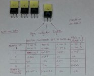
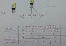
"IF" my understanding if correct and the 0.3-0.7V is true. That means the only transistor which is good is number 2.
The readings to 5&6 are identical which is quite suspicious,, maybe my conclusions and/or method of testing is not right.
That's it for the transistors for now, will have a look at the capacitors next.
What are your thoughts on whats been done and the readings I have obtained. Do you think the procedure is correct? If so what would you conclude? If you think my procedure is incorrect, where am I going wrong?
Thanks in advance.
Bass out
I started to take the transistors and capacitors off the board. I am writing this so that readers at the same electronics level as me
 , might be able to get a pointer or two.
 As a beginner, de-soldering is not as easy as it looks. I was expecting the de-soldering pump to suck the molten solder from a few millimetres away...NOPE not the case
 the nozzle of the de-soldering pump has to be ON the joint. After removing the component a quick wipe with some de-soldering wick is very useful, as it will clean any remaining solder, final stage is to wipe the board with cleaning alcohol.
Below is a picture showing the transistors and capacitors removed from the board:

The extent of the glue holding the capacitors down can now be clearly seen:

Using the wick helped remove most of the old solder, but I might give it another pass just before re-soldering.

The glue was easily removed. I don't think it was conductive, had more of a rubbery texture, so it pealed of like pva glue.

Now with the transistors off I looked at the data sheets I found on google and concluded that all the transistors were NPN with the following pin designation:


I followed the instructions I got from an online video to try and determine if the transistors were good or bad. In the picture below something like "+ ON B" means the positive terminal is on the base pin, so "- ON E" is negative terminal on emitter pin...etc
Transistors 1&2 are 2SC3182N
Transistors 3&4 are 2SA1265N
Transistors 5&6 are 2SD1508
I also learnt that when testing the transistors the multi-meter should be set to diode and one is to expect a voltage reading in the range of 0.3-0.7V or "OL" depending on the position of the terminals.
The below pictures show the readings I got with the various configurations :


"IF" my understanding if correct and the 0.3-0.7V is true. That means the only transistor which is good is number 2.
The readings to 5&6 are identical which is quite suspicious,, maybe my conclusions and/or method of testing is not right.
That's it for the transistors for now, will have a look at the capacitors next.
What are your thoughts on whats been done and the readings I have obtained. Do you think the procedure is correct? If so what would you conclude? If you think my procedure is incorrect, where am I going wrong?
Thanks in advance.
Bass out
Thank you for the Photographs, to remove the brown glue de-solder the large smoothing capacitors, any resistors that are covered in the glue need to be replaced.
The brown marks on the board are of no concern, it has only discoloured over time because the components are dissipating power hence the heat.
The blackened fuses show there is a short circuit which will be the output transistors you need to check each side.
I see the heat sinks are no longer attached, be aware the exposed metal on the back of the output transistors is not isolated.
What looks like white paper on the heat sink is actually a thermal transfer isolation strip called Mica.
You need to ensure that the output transistors are still isolated when you screw them back to the heat sinks.
If any area is ripped and metal is exposed you will need to fit additional Mica washers.
Also you can remove the flux after soldering by using flux remover or isopropyl alcohol.
Hello Audio Service,
Thanks for the info.
I suspected the white paper to be like a solid version of heat transfer paste, the fact that it acts as a insulator means I can't just remove it and use some paste. The original paper is not torn, but when put up against a light source you can clearly see parts of it have pealed off. So might be worth getting some more of that.
2SA1265N is a PNP transistors not NPN, so your base probe lead needs to swapped around.
2SD1508 is a Darlington Transistor two devices connected together to amplify the current.
Darlington transistor - Wikipedia.
Reviewing your test results confirms there is no issue with the 2SD1508 darlingtons.
The output transistors should be replaced.
2SD1508 is a Darlington Transistor two devices connected together to amplify the current.
Darlington transistor - Wikipedia.
Reviewing your test results confirms there is no issue with the 2SD1508 darlingtons.
The output transistors should be replaced.
Thanks for pointing that out.
Looking at the figures for the 2SC3182N, would you say it's ok?
If replacing three then might as well replace the forth. I ask this just to see if I understand the tabulated readings. The readings suggest it's ok...do you concur?
Looking at the figures for the 2SC3182N, would you say it's ok?
If replacing three then might as well replace the forth. I ask this just to see if I understand the tabulated readings. The readings suggest it's ok...do you concur?
2SA1265N is a PNP transistors not NPN, so your base probe lead needs to swapped around.
2SD1508 is a Darlington Transistor two devices connected together to amplify the current.
Darlington transistor - Wikipedia.
Reviewing your test results confirms there is no issue with the 2SD1508 darlingtons.
The output transistors should be replaced.
Also, is it normal to find all three (four) transistors need replacing? Or is this a result of my previous mishap.
What would be the symptom of a scenario where all four transistors have gone bad?
1 & 3 are short circuit so must be replaced.
2 looks good
4 retest with the meter probe on the base reversed.
I suspect only one channel has failed.
Normally if one output transistor on a channel has failed both should be replaced as internal damage may of occurred and the device could fail when under load even though it may test good with a meter or transistor tester.
Flux, resulting from quality solder, isn't any worry.
It's not corrosive, it's not conductive, it's inert.
It may be unsightly, yet it's harmless.
However, many people, and the internet self-proclaimed (obsessed perfectionists) guru's, have created the myth/law that it must be removed.
Us pro techs think that's funny.
Flux residue CAN be corrosive and conductive particularly if has been burned with subsequent rework. It's more of
a problem in high impedance circuits but you can not make a blanket statement that it is not a problem because
sometimes it is. I've only been doing this for 50 years so I haven't seen it all yet.
G²
1 & 3 are short circuit so must be replaced.
2 looks good
4 retest with the meter probe on the base reversed.
I suspect only one channel has failed.
Normally if one output transistor on a channel has failed both should be replaced as internal damage may of occurred and the device could fail when under load even though it may test good with a meter or transistor tester.
Audio Service thanks for you quick reply.
I have just retested and got the following readings:
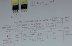
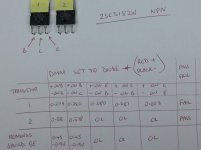
When arranged in their original position on the board the readings support the drop in volume in the left channel, which was what I was experiencing.
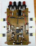
Could these shorted diodes result in the main fuse blowing? Or is that another issue?
Bass out
The shorted transistors would be the cause of the fuse blowing.
But there will also be resistors as advised before that will require replacing.
But there will also be resistors as advised before that will require replacing.
- Home
- Amplifiers
- Solid State
- Marantz PM66 SE keeps blowing fuse