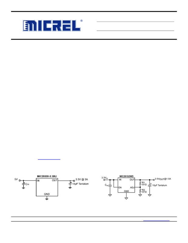
hi guys, i need some help. i am building a power supply for a mini pc based on this mic29752 regulator. what is not clear to me is how to choose the resistance values to get the desired output voltage. I would use a 15V transformer to get about 21V in to the regulator and I would like to go out with about 20V. there are infinite combinations to obtain this value, for example r1 = 1000ohm and r2 = 70ohm, but also r1 = 200ohm and r2 = 13ohm etc ... can you explain to me? thanks!
Accordi to datasheet: Vout=1,240 x (1+R1/R2)
Accordi to datasheet: Vout=1,240 x (1+R1/R2)
What is the problem you are trying to solve by using a linear power supply to begin with?
What sort of IEC appliance class are you aiming for?
Since the regulator is fairly noisy, there is little point in making R1 + R2 any lower than required to draw the specified minimum load current, 10 mA for this particular chip. That would be a total of 2 kOhms.
Exactly 20 V seems a bit hard to hit without going at least E96, at which point you could use e.g. 1.82k and 121R (note: rated power dissipation on 1.82k should be at least 0.4 W, so maybe a 1/2 watt type or two 1/4W in parallel).
hello thanks for the answer.
I have to power a pico psu hdplex for a mini pc for audio use.
I have no particular needs but I wanted something compact to put in a single case together with other linear power supplies (by mpaudio) that I already have for the dac and the usb cable.
do you think it is better a lt1083 from noise point of view?
otherwise what do you think of this switching psu?
https://docs.rs-online.com/05a8/A700000006464057.pdf
Last edited:
This is a Low-Dropout regulator -- and you have 15V to burn off as heat. In a small case getting rid of that heat will be an issue if you need more than a few dozen milliamps.
TI has a whole family of single-IC switching regulators, LM2575xxx, that might be worth considering since you want it compact. TO-263-5, easy to apply, quiet enough to be used on their Class D amp boards. You could then have individual LDO's for each circuit subsection, at a fraction of the waste heat.
In general, if you don't need LDO, don't choose LDO. Same with any specific-design-problem-solving part -- too often there are tradeoffs in other specs, including price.😉
Cheers
the pico psu accepts a voltage range from 16V to 24V, so I think the lm2575 family is not good (output up to 15V).
Why do you say I have 15V to burn as heat? I would have 21V input (transformer with 15V secondary) and about 20V output ... isn't it just 1V to burn in heat?
Why do you say I have 15V to burn as heat? I would have 21V input (transformer with 15V secondary) and about 20V output ... isn't it just 1V to burn in heat?
Sorry, my bad 😱 ..
Dunno where I got that *5V out* business.
You HAVE made a good choice! However, that doesn't leave much room for line voltage variations.
Regards
Dunno where I got that *5V out* business.
You HAVE made a good choice! However, that doesn't leave much room for line voltage variations.
Regards
Wish I could be more help there, but am not familiar with either device (LT1083 or mini pc).
Since the pico psu accepts 16 to 24V, is there a chance that you don't need regulation?
Either an unregulated linear or the 19V Meanwell brick should work. If there is still switching hash that needs eliminating, there are excellent filter projects on this forum.
Bricks are used more and more to power all sorts of diy projects. They are very cost-effective, allow a wide input voltage range, keep the line noise and dangerous potentials away from sensitive circuits and users, and usually satisfy the growing list of acronyms/safety approvals.
Cheers
Last edited:
yes in fact I don't need it to be adjustable.
my doubt on meanwell is that they declare 120mV of ripple ... isn't that a bit too much?
my doubt on meanwell is that they declare 120mV of ripple ... isn't that a bit too much?
Depends on what you're powering. Purely digital stuff often doesn't care. Single-ended analog does. So does mixed-signal if you're trying to achieve a low noise floor, say over 80dB or so.
But remember, this 120mV won't be 50/60Hz, it will be much higher frequency, and therefore more easily filtered. And being a brick you can kill it before it comes in and gets a hand-hold.
You could start a new thread, posing a general question on the Meanwell bricks. Others on this forum have used them, and probably have some good advice.
Regards
Last edited:
So in theory a pc (a totally digital motherboard) wouldn't be very much affected by ripple?
What do you mean by "being a brick ..." How can I filter this remaining ripple?
Thanks
What do you mean by "being a brick ..." How can I filter this remaining ripple?
Thanks
Last edited:
Sorry, that's just a slang term for an adapter that has its own power cord and chassis/case, then has another wire/cable that carries the regulated lower voltage to the device to be powered.
As to filtering, there's a project on this forum designed for this very task. It's by Mark Johnson, but I've forgotten the 6-character reference aGAIN!😱
The 16 - 24V supply range that you mentioned indicates that the board has its own regulation -- it is probably very tolerant of ugly power. At the very least, I would Make Sure that additional filtering is needed before spending the time and money.
Cheers
ok the fact is that building the power supply for me is more of a pastime than a real need, so maybe I opt to build the one with the mic29752. is it ok according to you r1 = 1820ohm 1/2W and r2 = 121ohm 1W?
Umm .. On the Micrel example you posted, R1 was Adj pin to Output, and R2 was Adj pin to ground. So, no that won't work. If you swap the values, it should give pretty close to the 20V you want but I'll have to review the data PDF to be sure. (Hope tommorow will be soon enough?)
One thing I do know for sure, though: Both resistors will conduct almost identical current, so the required power dissipation will be proportional to the resistance value.
Regards
One thing I do know for sure, though: Both resistors will conduct almost identical current, so the required power dissipation will be proportional to the resistance value.
Regards
sure, when you can ... the calculation to do is (r1 / r2 +1) x 1.24 right? so I am about 20V using the values 1820/121. Correct me if I'm wrong 🙂
Umm .. sorry, you are. The division needs to be applied the other way.
There's 98% of the same current through both resistors, so the only way to have 1,24V across one, and 18,65V across the other, is to have R1 be 121 ohms and R2 be the larger value - 1820 ohms.
That should give ~19,9 volts -- providing I didn't boot the arithmetic.
Cheers
There's 98% of the same current through both resistors, so the only way to have 1,24V across one, and 18,65V across the other, is to have R1 be 121 ohms and R2 be the larger value - 1820 ohms.
That should give ~19,9 volts -- providing I didn't boot the arithmetic.
Cheers
Last edited:
Note that these regulators don't behave like an LM317 (or 1117) but in fact have R1 and R2 reversed. Not an unusual sight among LDOs, actually. Makes it hard to build a capacitance multiplier with one, as I'd want to.
It depends on exact transformer, but in general with 15 VAC secondary you'll get abot 19VDC under load.I would have 21V input (transformer with 15V secondary)
- Home
- Amplifiers
- Power Supplies
- Mic29752 resistors help