I have been using this simple regulator for a few years, for pure convenience.
*the negative side is just mirrored.
But lately I have been interested in improving it. I have some questions:
1- Does this simple regulator(image simple-regulator) perform much less than popular regulators? Ex: LM371 / LM78xx / LM29xx
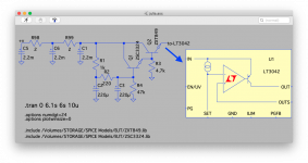
2- To use these new integrated ones like TPS7A4700, or even the LT3042, is it good to keep this part of primary regulation? (image lt3042)
* purpose is for low currents: headphone amp, pre amp, DAC/ADC...
*the negative side is just mirrored.
But lately I have been interested in improving it. I have some questions:
1- Does this simple regulator(image simple-regulator) perform much less than popular regulators? Ex: LM371 / LM78xx / LM29xx
2- To use these new integrated ones like TPS7A4700, or even the LT3042, is it good to keep this part of primary regulation? (image lt3042)
* purpose is for low currents: headphone amp, pre amp, DAC/ADC...
Attachments

Discrete regs can often beat out integrated ones in terms of HF rejection so it could make sense to put a discrete reg prior to an integrated one when the integrated one has poor HF rejection. But some of the newer integrated regs are looking quite good up to 1MHz or so, not sure how they do above that.
If you measure it's output pulsations or noise we can tell you the answer.1- Does this simple regulator(image simple-regulator) perform much less than popular regulators? Ex: LM371 / LM78xx / LM29xx.
The noise and pulsation of well-done LM317 can be lower then 0.1...0.5 mV RMS (it depends on a load).
If you measure it's output pulsations or noise we can tell you the answer.
The noise and pulsation of well-done LM317 can be lower then 0.1...0.5 mV RMS (it depends on a load).
I don't trust my oscilloscope below 1mv. As far as I was able to measure, the output ripple is below 1mV pk-pk.
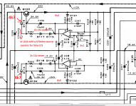
I think about doing some tests as shown in the second image, but as I have no way to take such accurate measurements ...
I prefer to ask the most experienced if I am in the right direction or not. 😕
Of cause it is impossible to measure a noise with an usual oscilloscope. I use AC millivoltmeter for this purpose, like, for example HP 400 series. (Actually, I use AC true RMS termal microvoltmeter, but an usual AC millivoltmeter may help too, because they usually have 1 mV scale).I don't trust my oscilloscope below 1mv. As far as I was able to measure, the output ripple is below 1mV pk-pk.
I think about doing some tests as shown in the second image, but as I have no way to take such accurate measurements ...
You could build up a low noise op amp circuit with a gain of, say, 10x, and AC couple that to your Vreg output and view the op amp's output on the scope for more sensitivity. I did this using two 9V batteries to get isolation from any possible ground loops. Short the input of this amp to gnd and see what the output looks like first. It should be a nice clean straight line. if you get that, then view your Vreg's output with it. Check your Vreg while its intended load is connected to it.
If you're needy, look for a girl.ok...then i live you in Batman's perfect audio world......
Thanks for the suggestion, I will build. 😀You could build up a low noise op amp circuit with a gain of, say, 10x, and AC couple that to your Vreg output and view the op amp's output on the scope for more sensitivity. I did this using two 9V batteries to get isolation from any possible ground loops. Short the input of this amp to gnd and see what the output looks like first. It should be a nice clean straight line. if you get that, then view your Vreg's output with it. Check your Vreg while its intended load is connected to it.
Hello,
I want to build a fixed regulator that will have an output of 24 volts DC with a current rating of 600mA or a little higher.
Wanna use a to220 type. Can be real fixed one or one that needs to be trimmed to 24 volts. I remember reading that some regulators have some garbage in their output. Do these regulators '' generate '' that garbage or is it coming from the power company and can they just not filter efficiently?
If i use a split bobbin transformer and a CRC or CLC ( 60 mH?) will it give a cleaner 24 volt output?
Greetings, eduard
the original series zener values for 24 v output are 14.1 ...15.5 v zeners hzs15s or rd15js /0.4w zener diodes.d113, d114 are E452 CRD (constant current)diodes which can be replaced with any handy 4.5...5ma current source like a a j112 with a 470 ohm source resistor.bf245c with probably 1kohm source resistor can do it...not exactly sure what's the resistor value for bf245c though...You can also use a 2k2...10 kohm resistor with a medium value of 4k7 doing the job, depending on transistor's hfe...You can also use a Darlington transistor there with a fine trimming of the feedback resistor's value for 24 v output and that resistor goes down.
Attachments
Last edited:
Hello,
I want to build a fixed regulator that will have an output of 24 volts DC with a current rating of 600mA or a little higher.
Wanna use a to220 type. Can be real fixed one or one that needs to be trimmed to 24 volts. I remember reading that some regulators have some garbage in their output. Do these regulators '' generate '' that garbage or is it coming from the power company and can they just not filter efficiently?
If i use a split bobbin transformer and a CRC or CLC ( 60 mH?) will it give a cleaner 24 volt output?
Greetings, eduard
The noise in a regulator like the LM317/337 originates in the reference voltage which is "gained up", and the error amplifier. The noise of the LM317/337 can be reduced with a 10uF capacitor from ADJ to GND.
A newish (now 8 years) design, the LT3080 uses a current source to drive an external resistance for the reference voltage. You can bypass this resistor for low noise. LT3080 is available in a 5-pin TO-220 and beats the LM317 hands down for PSRR and output impedance.
Oh, speaking of output impedance -- the CHOKE should go before the regulator, not after. Low output impedance is a characteristic of high quality regulators.
Hello,
Thank you!.
My idea of the CLC or CRC '' feeding '' the regulator was giving it a '' cleaner '' input maybe giving it an easier job.
Now i will see if i can find an actual circuit so i can make a point to point wiring on a breadboard.
As far as i understand the input cap should be close to the regulator circuit itself. Sometimes it helps to add a cap at the output to get some additional noise filtering.
What kind of cap and value to use for bypassing that external resistor?
Greetings, Eduard
You may wanna try the Technics denoiser ...just 7815 and 7915, two 5.1 zener to raise the output to 25v and the op-amp feedback if you want aminimum of 20db additional noise reduction...
https://www.diyaudio.com/forums/power-supplies/359652-fine-ic-voltage-regulators-28.html#post6353344
https://www.diyaudio.com/forums/power-supplies/359652-fine-ic-voltage-regulators-28.html#post6353344
I avoid using CLC because for low currents the inductance value will have to be high to have an effect, which will result in a component large enough to be disproportionate to the rest of the circuit. If you don't mind it, the performance is actually a little better...Hello,
Thank you!.
My idea of the CLC or CRC '' feeding '' the regulator was giving it a '' cleaner '' input maybe giving it an easier job.
Now I understand your lack of patience, another topic had already been created recently with the same subject where you would have already been stressed.You may wanna try the Technics denoiser ...just 7815 and 7915, two 5.1 zener to raise the output to 25v and the op-amp feedback if you want aminimum of 20db additional noise reduction...
https://www.diyaudio.com/forums/power-supplies/359652-fine-ic-voltage-regulators-28.html#post6353344
Thank you anyway. 🙂
The noise in a regulator like the LM317/337 originates in the reference voltage which is "gained up", and the error amplifier. The noise of the LM317/337 can be reduced with a 10uF capacitor from ADJ to GND.
A newish (now 8 years) design, the LT3080 uses a current source to drive an external resistance for the reference voltage. You can bypass this resistor for low noise. LT3080 is available in a 5-pin TO-220 and beats the LM317 hands down for PSRR and output impedance.
Oh, speaking of output impedance -- the CHOKE should go before the regulator, not after. Low output impedance is a characteristic of high quality regulators.
Just a note: make sure to apply a minimal load to LT3080 like a power on LED otherwise it puts out full input voltage. Not that it is critical but one keeps measuring the same fault while measuring a new board 🙂
Last edited:
Hello,
I will put a resistor across the output so there will be let us say 10mA load all the time.
Probably all the parts which make up the input voltage will be close to the regulator. At least the last capacitor will be a at a few centimeters
I think the load will be at 10 to max 20 centimeters.
Probably can have it the other way round to with the " preregulation " being at greater distance..
What are the values of the components i need to add around the regulator to compose something that can supply 24 volts at 400 mA nominal load. In sleep mode the current will be 5 mA and in standby mode the current will be 20 mA
I wanna mount most parts on a kind of breadboard so a " real life drawing " would be very nice.
Thanks in advance. Greetings,Eduard
Hello,
Forgot to answer about CLC.
I actually use a lot of choke input circuits and so far no matter what the circuit was that needed a voltage to do its job it always was an improvement.
I actually have a 1000mH 1A 9ohm dcr doing nothing so i wanna try using it.
Greetings,Eduard
Forgot to answer about CLC.
I actually use a lot of choke input circuits and so far no matter what the circuit was that needed a voltage to do its job it always was an improvement.
I actually have a 1000mH 1A 9ohm dcr doing nothing so i wanna try using it.
Greetings,Eduard
there are actually 3 or 4 topics on the same subject where the same people run the same ideas...i found this 30 years old circuit recently and i was amazed why people didn't noticed it as it's very simple and effective.Now I understand your lack of patience, another topic had already been created recently with the same subject where you would have already been stressed.
Thank you anyway. 🙂
- Home
- Amplifiers
- Power Supplies
- Simple Linear Regulator? New IC Regulator?