Hey all,
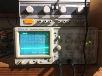
I’m having a very strange issue. I am repairing a Mitchell Pro 100 guitar amp for someone. If you don’t know the amp, it’s a push pull guitar amp powered by four 6L6GC power tubes. Here’s the problem: I run a .8V sine wave at around 1500Hz and follow the signal path with my oscilloscope. Everything checks out until I get to the output tubes. The sine wave is perfect on the grid of each 6L6 but on the anode there is nothing but noise (see photo, top wave is grid bottom is anode). The voltages on the tube pins seem normal. Heater - 5.5V AC, Anode - 519V DC, Screen Grid - 513V DC. Any thoughts?
I’m having a very strange issue. I am repairing a Mitchell Pro 100 guitar amp for someone. If you don’t know the amp, it’s a push pull guitar amp powered by four 6L6GC power tubes. Here’s the problem: I run a .8V sine wave at around 1500Hz and follow the signal path with my oscilloscope. Everything checks out until I get to the output tubes. The sine wave is perfect on the grid of each 6L6 but on the anode there is nothing but noise (see photo, top wave is grid bottom is anode). The voltages on the tube pins seem normal. Heater - 5.5V AC, Anode - 519V DC, Screen Grid - 513V DC. Any thoughts?
Are the cathodes seeing a complete path to ground?
WHAT photos?
What amplitude is signal at grid?
WHAT photos?
What amplitude is signal at grid?
Yes the cathodes are all tied to ground.
The amplitude of the signal on the grid looks to be about 5V peak to peak. The signal entered the amplifier at .8V so it has definitely been amplified by the preamp.
Maybe you can see the photo now.
The amplitude of the signal on the grid looks to be about 5V peak to peak. The signal entered the amplifier at .8V so it has definitely been amplified by the preamp.
Maybe you can see the photo now.
Attachments
1.
Yes the heater voltage on each output tube is 5.5V AC.
2.
Which resistor are you referring to?
Yes the heater voltage on each output tube is 5.5V AC.
2.
Which resistor are you referring to?
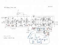
Some of the mods make little or no sense
Power amp as shown is practically unity gain, I mean at power tube plates, so drive signal needs to be in the order of hundreds of volts.
What is bias voltage at power tube grids? (pin 5)
What is bias voltage at junction of 220k bias resistors?
Is any load connected at speaker out jacks?
Are they shorted by any chance?
Yea I know, this amp is stock so all of the hand scribbled notes do not apply.
By drive signal you just mean whatever source that is plugged into the input right? In this case it was a .8V sine wave not cranked, I wanted to keep the wave clean. If I really crank it the signal *on the grid* gets much larger.
Pin 5 reads -83V
220k junction reads -85V
Yes there is an 8 ohm dummy load connected, not shorted.
Last edited:
Biased at -85 V the 6L6GC's are completely cut off. No wonder there's no signal appearing at their plates. The correct control grid bias voltage should be expected in the -35 to -40 V range for these tubes. Check the bias supply circuitry!
Best regards!
Best regards!
1.
Yes the heater voltage on each output tube is 5.5V AC.
2.
Which resistor are you referring to?
Edited my post, when I realised there is none 🙂
See above post, explains it all
However, the heater voltage is also too low, outside the +/-10% range, so emission may be weak too.
Last edited:
So I fixed the voltage on the control grid, now it's at -54V and the schematic calls for -52V so I think it's good there.
Then I noticed something else. I measured the output transformer with the (with the leads unsoldered) from center tap to each end and one is at 80 ohms and one is at 40 ohms. 50% seems like a problematic difference in resistance. When I measured the bias, two of the tubes are at 27mA and the other two are at 43mA. I'm thinking this could be related to my problem.
Then I noticed something else. I measured the output transformer with the (with the leads unsoldered) from center tap to each end and one is at 80 ohms and one is at 40 ohms. 50% seems like a problematic difference in resistance. When I measured the bias, two of the tubes are at 27mA and the other two are at 43mA. I'm thinking this could be related to my problem.
Those power tubes are completely cut off.Pin 5 reads -83V 😱
220k junction reads -85V 😱
Yes there is an 8 ohm dummy load connected, not shorted.
They won´t even notice a hammer to the glass tube, let alone a puny signal at the grids.
EDIT:
If schematic asks for -52 V then by all means supply that.
Didn´t you check that before?
Bias voltage is PARAMOUNT.
And you leave us without answers: does it WORK now or not?
EDIT 2:
That´s fine for EL34; for 6L6 classic is around -52V.The correct control grid bias voltage should be expected in the -35 to -40 V range for these tubes.
Last edited:
The screen grid is very high, around 480V. The control grid is at -54V like the schematic asks for.
And no, it still doesn't work.
I checked the OT and there is a discrepancy. From center tap one end is 80 ohms and from center tap to the other end is 40 ohms. Seems like the problem.
And no, it still doesn't work.
I checked the OT and there is a discrepancy. From center tap one end is 80 ohms and from center tap to the other end is 40 ohms. Seems like the problem.
The difference in winding resistance does seem high, but not completely out of line. EI cored trafos can have different winding lengths to get the same number of turns on either side of a center tap. But there also could be a partial short (some windings shorted). Easy enough to check for - feed in about 10 watts into the output, in parallel with a speaker (from a good small solid state amp). If there are shorted windings, the amp will current limit and distort. If the transformer is good, you will see equal voltages on either side of the center tap, and the transformer will not add much loading (a speaker in parallel with it will sound normal). Don’t actually touch them during the test, the voltage will be high enough to hurt or kill. Use clips and only energize it when your fingers are away.
Strange, as your schematics shown in #4 doesn't tell anything.So I fixed the voltage on the control grid, now it's at -54V and the schematic calls for -52V so I think it's good there.
Strange again, as the GE 6L6GC datasheet (https://tubedata.tubes.se/sheets/093/6/6L6GC.pdf) tells -37V for the maximum bias voltage reading.That´s fine for EL34; for 6L6 classic is around -52V.
Best regards!
Are you sure about -37V being a maximum value?
I think the -37V from the datasheet is just the negative voltage fitting to the rest of the stated values (among them: Vg2 = 400V).
Vg2 max in pentode mode is 450V but my guess is that even this limit is violated in some (many?) amps.
I think the -37V from the datasheet is just the negative voltage fitting to the rest of the stated values (among them: Vg2 = 400V).
Vg2 max in pentode mode is 450V but my guess is that even this limit is violated in some (many?) amps.
Last edited:
I meant the maximum value, as shown in the DS. All other bias values' amounts are lower than 37 V.
Best regards!
Best regards!
But if a design runs the 6L6GC's with Vg2 = 450V (or even higher) than it's normal for Vg1 to be more negative than -37V.
Two examples:
Fender Bandmaster 6G7 (Vg1 = -55V)
Fender Bassman 59 (Vg1 = -54.5V)
Two examples:
Fender Bandmaster 6G7 (Vg1 = -55V)
Fender Bassman 59 (Vg1 = -54.5V)
- Home
- Live Sound
- Instruments and Amps
- No signal on 6L6 plate!! HELP