Today's project: find a +15VDC power brick and put it to work matching transistors.
Part to be adapted: Oram AL-16(t)
I searched through my box o' adapters and found plenty of +5/6/9/12VDC bricks but only one that said +15VDC, the above mentioned Oram. This was taken from an old Fujitsu Speedport ADSL modem kit. I couldn't use it as-is, because it wasn't just +15VDC, it was also -15 as well as +3.5 and +5. Not only that but the cable ended in an 8 pin connector similar to DIN.
Since I didn't have the Speedport schematic (and they apparently don't exist online) I simply cut the end off the cable and figured I'd test until I found the taps I needed. Ha ha. Yeah.
I found 8 wires of various colors, plus a bare (or as we called it in the business, "drain") wire. Using the drain as ground (since it went to the outer jacket of the DIN connector) I found the following values:
White +13.51
Black -13.51
Orange +5.159
Brown +5.159
Yellow +3.505
Blue +3.505
Red 0
Green 0
The first thing that jumps out is that I can use this brick to get very close to two of the rated voltages but it's 1.5v off my desired 15v output. I've also found that I can skip the drain wire, connect the black wire to my DMM negative probe, and get a whole bunch of other voltages ranging from +1.5 to +18. I can switch to the white wire and get some negative values. I can also measure across some of the different colors and get +10vdc.
At no point can I mix and match anything to get +15vdc, or at least I haven't found the right combination yet. I don't really want to mess around with that because sometimes joining two wires on the same probe sometimes results in a really warm wire, which is no bueno.
Given what I've told you about this brick - that it has 4 taps, 8 wires plus a drain, and the initial voltages I list above - if anyone here could recommend some plan of attack to find the correct hookups to get the 15vdc output I would really appreciate it.
And yes, I know I can just buy a 15v laptop brick for under $20 and be done with this, but I'd like to learn more about these multi-tap power supplies.
Last edited:
First the drain wire may only connect to a shield in the box and possibly the safety ground if not double shielded.
Second the voltages may be only accurate at all under full load and the shown value is a minimum. And it may have remote sensing (not sure why on something like that).
Second the voltages may be only accurate at all under full load and the shown value is a minimum. And it may have remote sensing (not sure why on something like that).
There was a shield in the jacket, the typical silver side/ blue side metal foil. I'm sorry I didn't mention that.
It's a switcher, so, you'll need to load sat the +5V output to, say, 1A. Then see what the +/- 15V outs read. You confused me for a few by typing
Brown -5.159
I looked it up on ebay and there's only a + 5.1V out.
Brown -5.159
I looked it up on ebay and there's only a + 5.1V out.
It's a switcher, so, you'll need to load sat the +5V output to, say, 1A. Then see what the +/- 15V outs read. You confused me for a few by typing
Brown -5.159
I looked it up on ebay and there's only a + 5.1V out.
Thanks for pointing that out, I fixed it. To be clear, the only negative value is the second 15v line which is the black wire (-13.51 actual).
So when you say its a switcher, what does that mean, and why would I need to load up one particular output to affect the other?
It would be fun and possibly instructive to answer all your questions about the Oram AL-16 supply (assuming someone out there actually knows them, so that the rest of us aren't reduced to looking up IC numbers and generating hypotheses), but offline power supplies have become extremely sophisticated and high density over the last decade or two. In the absence of the designed load it is almost certainly 'falling back' into one of several alternate operating modes, at least one of which may be to satisfy Power Factor Correction imperatives. All the others provide only intermittent pulses. Since your project is test equipment, stability is essential. Set this brick aside for a future project that it is better suited for.
Meanwhile, in less time than it took you to cut off the 8-pin connector, take the measurements, ponder it a bit, and make the post, you could cobble up a simple 15V, 1 or 2A linear supply that would satisfy the project requirements, would be dead-stable irrespective of load(s), and you wouldn't have to expend another moments' thought concerning it!😉
Regards
Meanwhile, in less time than it took you to cut off the 8-pin connector, take the measurements, ponder it a bit, and make the post, you could cobble up a simple 15V, 1 or 2A linear supply that would satisfy the project requirements, would be dead-stable irrespective of load(s), and you wouldn't have to expend another moments' thought concerning it!😉
Thats awesome!! Instead of wasting my time trying to make an already finished supply do what its supposed to do, I could spend a day on Youtube looking at videos of how to build a power supply, another few hours ordering components, a few days waiting for them, and then some more time putting it all together, followed by several hours diagnosing things when it inevitably doesn't work!
Stay tuned for part 2, when I ask Rick the best way to figure out the firing order on my new distributor and I learn I should just build another vehicle!
j/k Rick... 😀
I presume you wouldn't have said what you did if there wasn't some easy way to build that power supply out of old eggshells and discarded tennis shoes. So what's the skinny on this 15v per supply?
I wouldn't start on UTube.😱
And you did have to ask what it meant that *it's a switcher*, along with the *loaded vs unloaded outputs* question. I'm sorry, but that spells *unfamiliar with multi-secondary, high-frequency transformers*, let alone *not familiar with advanced offline convertor design*.
Let's start with specifying the requirements. One question I have is why, if you need 15V, 13.8V is not acceptable? Also, what are the current requirements? Most transistor testing can be accomplished with a few hundred milliamps. Easy peezy, as a popular English soccer announcer often says.
Aren't you going to have to order parts and wait for them to arrive to build the rest of the tester?
Cheers
Attachments
Suggest you lose some attitude if you want help to keep flowing.Thats awesome!! Instead of wasting my time trying to make an already finished supply do what its supposed to do, I could spend a day on Youtube looking at videos of how to build a power supply, another few hours ordering components, a few days waiting for them, and then some more time putting it all together, followed by several hours diagnosing things when it inevitably doesn't work!
Stay tuned for part 2, when I ask Rick the best way to figure out the firing order on my new distributor and I learn I should just build another vehicle!
Help you desperately need.
It IS already doing what it is supposed to do, meaning supply:an already finished supply do what its supposed to do
Any of those work fine for you?White +13.51
Black -13.51
Orange +5.159
Brown +5.159
Yellow +3.505
Blue +3.505
Red 0
Green 0
If so, congratulations, the thread ends here. 😛
If not, you will have to mod it (if possible) or build something new.
In any case you will have to order something and wait.
If you have a Diesel engine you won´t have much use for your distributor, you might have to build a gas engine.Stay tuned for part 2, when I ask Rick the best way to figure out the firing order on my new distributor and I learn I should just build another vehicle!
OK, post the schematic of your transistor matcher, it *might* work fine with 13.5V which you DO have available.
And what kind of transistors are you matching?
My goodness...
In fairness, if you are experienced enough to need transistor matching, one might reasonably assume building a simple power supply would not be a challenge.
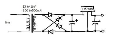
Transformer, rectifier, filter cap, optional regulator.
In fairness, if you are experienced enough to need transistor matching, one might reasonably assume building a simple power supply would not be a challenge.
Transformer, rectifier, filter cap, optional regulator.
I could tell it's a switcher by the 100 - 240 AC input voltage range printed on the label. Considering the currents on each output it can support, I suspect zero on all of them was not a design requirement. So if you have an 8 ohm power resistor for testing amplifiers, you can connect that to the +5V as a "minimum" load. Then I bet the +/- 15s will read closer to +/- 15.
I could tell it's a switcher by the 100 - 240 AC input voltage range printed on the label.
Great! Could you please tell me what you mean by "switcher", then? I've seen those voltage ranges or close to it on many bricks for the past 20 years or more.
Considering the currents on each output it can support, I suspect zero on all of them was not a design requirement. So if you have an 8 ohm power resistor for testing amplifiers, you can connect that to the +5V as a "minimum" load. Then I bet the +/- 15s will read closer to +/- 15.
Again, how would the currents tell you that?
Anyway, after re-reading your original comment last night, I started thinking maybe there was some stand-by mode this thing was looking for, where an initial load got the brick ready for full service, and maybe thats what you were talking about. I don't have the dummy load you're talking about but I have plenty of pulls from other projects I've wrecked and abandoned, so I grabbed one and hooked it on the 5v line and used the red wire as a ground for it. No change on the meter for the 15v line. I switched it to the green wire and then the drain and got the same result. I also tried the 3.5v line and didn't get any change in voltage.
In any case, why would the manufacturer specify a brick that does this, and why would there be any advantage in it? Wouldn't it be easier to have a brick that produces all four rated voltages to an open measurement, and then have all the fun stuff inside the ADSL modem, like regulating down the big line until the subsystems on the small lines get loaded up?
I wouldn't start on UTube.😱
Why? Sometimes its easier to show someone than to spell it out. I didn't understand rectifier bridges until recently, as a result of a video. I didn't understand what a transistor does until I saw an animation. I've been reading about electronics for years yet it took videos for me to understand some of it. Text helps in a lot of places where the video is just noise to me, btw, so I don't discount reading, believe me.
And you did have to ask what it meant that *it's a switcher*, along with the *loaded vs unloaded outputs* question. I'm sorry, but that spells *unfamiliar with multi-secondary, high-frequency transformers*, let alone *not familiar with advanced offline convertor design*.
Yeahhhhh, so thats why I'm asking questions...

Like...
Multi-secondary I get. I've redone a few AC supplies for big pieces. I still lose my mind going over the charts that allow wiring 6 different ways but in the end they all worked. High-frequency, I don't get. This is all 60Hz, which is far from high frequency, so you must be referring to something else.
And... "offline convertor design"?? Thats a new one for me.
Let's start with specifying the requirements. One question I have is why, if you need 15V, 13.8V is not acceptable? Also, what are the current requirements? Most transistor testing can be accomplished with a few hundred milliamps.
I have no idea. The spec for the design calls for 15v and 500mA. I was going to use a 16v supply I found laying around here, because my default mode is "This is good enough", but then my super-secret default foundation mode is "Must be precise!" kicks in and says "Dude that wrote the spec knows more about electronics than I know about sleeping and eating, so do what he says!" So I dug around till I found that 15v supply. And here we are.
The reason I'm trying to understand the thing is directly because of my previous work with multi-tap appliance transformers. Potential output ranged from 100v-240v, and by moving a few wires around and working the individual coils in series and parallel I could get all those different outputs. I figured that since I got two of the three rated voltages out of this transformer, but I was short on the third, that it was possible that adding a few more wires to the mix might get me to 15v. I had a great time experimenting with different wire arrangements and got voltages from 1.5x up to 26v, with a bunch of interesting stops along the way. No 15v though. I don't like this brick much, right now.
Where did you get 13.8v, btw? None of the taps on this thing is producing over 13.51.
Easy peezy, as a popular English soccer announcer often says.
Is that where that creepy saying came from? Who is the announcer? I may take up watching soccer just so I can openly mock the guy. I didn't hear that phrase before a couple of years ago, and then it was everywhere - I heard it in a few shows, people I know used it in random conversations, and it even turned up in magazine and online articles. It really grates on me.
Aren't you going to have to order parts and wait for them to arrive to build the rest of the tester?
No, I have the complete parts list here. Its like, a few wires a 2.2k resistor and a breadboard. And +15vdc, if I get this stupid brick working right.
Cheers
Gracias!
My goodness...
In fairness, if you are experienced enough to need transistor matching, one might reasonably assume building a simple power supply would not be a challenge.
Transformer, rectifier, filter cap, optional regulator.
I'm doing the transistor matching to get experience. I know how a basic supply works, except for the voltage regulator chip (LM12343198776etc). In any case, I would think sticking a transistor in a breadboard and measuring VGS is a heck of a lot less complex than building a power supply. I don't even have to pick up a soldering iron to do what I need with this.
Last edited:
Suggest you lose some attitude if you want help to keep flowing.
Help you desperately need.
OOh...maybe look at the "JK" and realize I was being funny? Rick seemed to get it.
I have a really difficult time with learning electronics. I've been at it for years and the amount of effort I expend for a little result could be either damaging or humorous, so I choose humor. Once you understand that, we're going to get along fine.
I don't desperately need the help. Like I said, I can go buy a 15v laptop power supply a lot easier than trying to build my own power supply. I saw this brick here with my preferred rated voltage stamped on the back, saw a bunch of extra wires, thought "this shouldn't be difficult - isolate the wires that give me my voltage and done". And of course, like everything else I do with electronics, it didn't work out that way. I'm trying to learn here.
It IS already doing what it is supposed to do, meaning supply:
Any of those work fine for you?
No, given that I wanted 15v, which is what its supposed to do, but isn't.
If so, congratulations, the thread ends here. 😛
Correction: if I got what I wanted from the brick in the first place there wouldn't have been a thread to begin with.
If not, you will have to mod it (if possible) or build something new.
In any case you will have to order something and wait.
I believe I'll have a cheeseburger and fries. Thats worth waiting for.
If you have a Diesel engine you won´t have much use for your distributor, you might have to build a gas engine.
You get the gold medal in the "non sequitur" category.
OK, post the schematic of your transistor matcher, it *might* work fine with 13.5V which you DO have available.
And what kind of transistors are you matching?
Mosfets, using the DIY that Nelson Pass posted, which is probably one of the more famous docs here and on his site. I would be almost certain you've seen it before and know its pretty basic. I know that if I type "matching mosfets" in a search, the only thing that comes up is that article, along with articles from people quoting it, paraphrasing it, and stealing it outright.
PassDiy
Like I said to Rick, above: its a few wires and a resistor on a breadboard. And +15v.
I'm sure there's a technical reason why Nelson would want 15v and not 13.5v - or 12v (most common bricks I see) or 9v (batteries I have in my drawer). I think it'd be easier to just do what he asks.
Well I'm surprised - and not - that the +15V value didnt change with a load on +5... You didnt mention the Ohms value you used, so if it was 1k, that would cover the doubt. You need something like 5 ohms, 8 being more common amongst audiophiles.
A "switcher" is basically a class D in powersupply clothing. It uses a pulse-width scheme to regulate. In the most basic design (i.e. "cheap") everything works fine - as long as current flows out. With no current flow, the class D PWM controller chip doesnt know what to do. I have one PC powersupply that "pulses" the DC voltage output with zero current load - in its confusion as to what's going on.
Like the PC power supply, in the intended application for this brick, there's never the case of zero output current, as it's always connected to the powered-on modem device to be useful. So that problem goes away - at least as far as the OEM is concerned.
Switching power supplies are popular because, generally;
- They have the wide-range AC input, so the OEM doesnt have to stock and manage different SKUs for Europe, China and the US.
- They are typically lighter than an ordinary 50-60 Hz transformer based equivalent, so the OEM saves on shipping their product.
- They can have very good regulation over AC line variations, so the OEM doesnt have to make special, explicit circuitry in their product to take care of that.
Considering that you want to explore matching transistors, I'd suggest using the best-behaved power supply you can find - just to get that out of the picture you're trying to take of the transistor. For npn / n-channel, you'll be sinking current at the transistor output and will need a power supply capable of sourcing the current you expect to sink.
At the transistor input, you'll need to provide a current (npn) or voltage (n-channel). The input current may be 1/10 to 1/1000 of the output, so different requirement there. For a FET, the input is voltage and no continuous current is needed. It may be a good idea to use even a different power supply unit for the input part of your tester, so it remains totally unaffected as the output current increases during your test...
I'd suggest an analog, transformer based PSU for the input and a switcher capable of multi amps for the output. The switcher can be "preloaded" using resistors such that it's voltage-stable with zero load being drawn from your transistor under test. I'm imagining an ATX computer power supply, for the cheapest implementation. Use the output with the highest label current capability.
The input PSU would need to be somewhere above 10V to fully test most FETs. The current capability depends on the circuit you're using to drive voltage or current into the FET / Bipolar transistor under test. For example, if the input control was a 50 Ohm pot, the power supply would need to provide better than Vout/50 of continuous current. So if Vout was "15", that'd be 300 mA. Probably pretty easy to find something analog that can do anything above 10V, and 500 mA regulated. Regulated meaning the voltage output value stays the same as current increases from 0 - 500 mA.
Ela-blah-ating further, some PC power supply boxes have two 12V channels; one for the CPU (higher current) and one for the rest of the motherboard. It's conceivable to successfully "preload" the +5V output with an amp or two for stable operation, then use one +12V channel for the tester input control circuit - and the higher current one for driving the output current measurement. Cleverly arranged, the PSU cooling fan could even cool the heatsink you mount the device under test upon. Maybe even use the CPU HS for this, from the old 1200 "specmark" AMD Athalon box you butchered to make your transistor matcher.
Hope this helps and good luck!
Last edited:
Well I'm surprised - and not - that the +15V value didnt change with a load on +5... You didnt mention the Ohms value you used, so if it was 1k, that would cover the doubt. You need something like 5 ohms, 8 being more common amongst audiophiles.
Forgive me, I should have listed that value. I have a small pile of resistors out of an old receiver I wasn't able to repair. These are 13 and 20ohms, 1/2 watt. I grabbed one at random.
BTW, I asked earlier why you chose the +5v for the load. Why not the +3.5V? And should I have loaded up both taps, and maybe the -13.5 as well?
A "switcher" is basically a class D in powersupply clothing. It uses a pulse-width scheme to regulate. In the most basic design (i.e. "cheap") everything works fine - as long as current flows out. With no current flow, the class D PWM controller chip doesnt know what to do. I have one PC powersupply that "pulses" the DC voltage output with zero current load.
Like the PC power supply, in the intended application for this brick, there's never the case of zero output current, as it's always connected to the modem device to be useful. So that problem goes away - at least as far as the OEM is concerned.
I get what you're saying, but wouldn't the DMM (when used to complete the circuit instead of just measuring across it) be considered a meaningful load, even if it was very minimal?
Switching power supplies are popular because, generally;
- They have the wide-range AC input, so the OEM doesnt have to stock different SKUs for Europe, China and the US.
- They are typically lighter than an ordinary 50-60 Hz transformer based equivalent, so the OEM saves on shipping their product.
- They can have very good regulation over AC line variations, so the OEM doesnt have to make special, explicit circuitry in their product to take care of that.
Interesting. Thank you for the info.
Considering that you want to explore matching transistors, I'd suggest using the best-behaved power supply you can find - just to get that out of the picture you're trying to take of the transistor. For npn / n-channel, you'll be sinking current at the transistor output and will need a power supply capable of sourcing the current you expect to sink.
The goodie I'm using for this project is listed as "N-Channel, Enhancement-Mode, Vertical DMOS FET". It'll be used as an input transistor in a differential pair. Like I have any idea what its doing, but I have to learn. Right now, I know I have to match these things as closely as possible.
At the transistor input, you'll need to provide a current (npn) or voltage (n-channel). The input current may be 1/10 to 1/1000 of the output, so different requirement there. For a FET, the input is voltage and no continuous current is needed. It may be a good idea to use even a different power supply unit for the input part of your tester, so it remains totally unaffected as the output current increases during your test...
Well thats interesting. You suggest using that for just testing mosfets, when there's no variance in signal or inductive load, or any of the other stuff I don't understand? I'm not arguing against it - I've heard about amp designs like that, where the input sub is isolated on its own board and has its own power supply. I find it an interesting idea, since I'm all about precision (down below my surface brain of "ehhh, good enough".
I'd suggest an analog, transformer based PSU for the input and a switcher capable of multi amps for the output. The switcher can be "preloaded" using resistors such that it's voltage-stable with zero load being drawn from your transistor under test. I'm imagining an ATX computer power supply, for the cheapest implementation. Use the output with the highest label current capability.
The input PSU would need to be somewhere above 10V to fully test most FETs. The current capability depends on the circuit you're using to drive voltage or current into the FET / Bipolar transistor under test. For example, if the input control was a 50 Ohm pot, the power supply would need to provide better than Vout/50 of continuous current. So if Vout was "15", that'd be 300 mA. Probably pretty easy to find something that can do anything above 10V, and 500 mA regulated. Regulated meaning the voltage output value stays the same as current increases from 0 - 500 mA.
In Nelson's diagram, its +15v to a resistor, which then goes into the drain and gate, plus a line going from the source to ground, which I assume in this case means the negative side of the power supply. There's a test point after the resistor, and before the ground. His resistor value is 2200. Using your formula I have 15/2200, or... 6mA? Can that be right?
Actually, I guess thats right. Reading Nelson's article - for the 50th #(!* time - I see he's using that exact formula to test his N channel devices at 5mA.
Is there any reason why I'm testing these things at such a tiny current and not much more voltage than a clock radio, when the input board on the amp they'll be used in might run 50v, 60v, 70v, etc..?
Ela-blah-ating further, some PC power supply boxes have two 12V channels; one for the CPU (higher current) and one for the rest of the motherboard. It's conceivable to successfully "preload" the +5V output with an amp or two for stable operation, then use one +12V channel for the tester input control circuit - and the higher current one for driving the output current measurement. Cleverly arranged, the PSU cooling fan could even cool the heatsink you mount the device under test upon. Maybe even use the CPU HS for this, from the old 1200 "specmark" AMD Athalon box you butchered to make your transistor matcher.
I think you have me mixed up with someone else - the last AMD I had was almost 20 years ago and its long gone - I never used it for any projects.
Hope this helps and good luck!
It does, believe it or not. I'm really frustrated with how difficult its been for me to absorb this so I'm glad for any path you can offer. So, thanks for your help and your good humor, JJ, it makes all the difference to my young brain.
It does, believe it or not. I'm really frustrated with how difficult its been for me to absorb this so I'm glad for any path you can offer. So, thanks for your help and your good humor, JJ, it makes all the difference to my young brain.
Hi Talon,
Don't be frustrated/discouraged!
Electronic design is an enormous field, but all of us began knowing nothing. I have 5.5 years of college learning, and a life of design experience; now I'm retired, soon 73, and I'm still learning. The learning is part of the fun.
Persist and enjoy the journey!
Good luck!
Steve
Thanks Steve, I appreciate the encouragement. I don't really get discouraged about this anymore, but I do get very frustrated. There has to be a reason why I have to work so hard to learn this, but I haven't figured it out yet. Once I do its just a matter of re-wiring my brain to learn the right way. Until then, I rack up an impressive amount of failed projects and each time, I learn how not to do something. 😀
+1 BSST -- but I'll have to almost leave it at that 'til I get caught up on some reading (the last dozen or so posts).
Talon, you're clearly a gifted writer and capable problem solver -- I was hooked by your OP. Use one of the 13,51V pairs (sorry about the 13,8 typo), finish the transistor matcher, learn some more great stuff, and let's save the magic of offline convertor design for another time.
Regards
edit: oops, forgot -- Ray Hudson, IIRC, BeIN Sports.
Last edited:
Talon, I have been soldering over 65 years now, and I still learn things every day.
A "switcher" is slang for "Switchmode power supply" also called SMPS. It does not run at 60Hz. Linear supplies run at 60Hz - those are the classic transformer, rectifier and filter cap things. A SMPS rectifies and filters the mains - your AC from the wall outlets - which it THEN switches off and on at high frequency through a MUCH smaller transformer. In a typical ,linear supply, the filter caps are recharged 120 times a second. They have to provide current to the circuit for 1/120 of a second at a time. A switcher can run at 50kHz, 100kHz, even into the megahertzes. The caps there thus are recharged every 100,000th of a second and so can be much smaller.
The SMPS lacks the huge iron transformer, so it weighs FAR less. It also runs at very high efficiency. The large iron transformer is also relatively expensive. A whole SMPS can cost a lot less than just a transformer. SOmeone had to design the circuit, but they are assembled by machine, not people with soldering irons. SO the complexity doesn't matter.
You keep referring to a "brick", and I have to admit I don't know what a brick is. DO you mean a "power adapter" like comes with so many things? What we call a "wall wart?" Or do you mean a box supply like bolts into a desk top computer? (Those by the say ARE SMPS) Point being, the whole using terms unfamiliar works both ways.
A linear supply has a transformer that steps the mains voltage - 120vAC here - down to something lower and then rectifies it. If I plug that into a 240v outlet, all the voltages inside it will be doubled. And if it is a 15v supply, that means 30v will come out. An SMPS can accept either 120v or 240v mains input at the flip of a switch. But more modern ones accept that full range of voltage with NO other compensation. By its nature, a linear supply cannot do that. And that is why jj knew what he knew.
For multi output supplies like in your computer, the +5v output is the main one, so if any output needs a load it would be that one. WHy would it need a load? Because the regulation only needs to be within a small range. With zero load required, then it has to regulate over a wider range. Needing a load isn't a feature, it is a side effect. The SMPS is not used with nothing connected as a load, so needing one is not an issue.
- Home
- Design & Build
- Equipment & Tools
- Please help me adapt a power brick for bench work