I want to change triode OPT loaded for CCS loaded & using the OPT to reduce output impedance but I have doubts:
1-It's needed parafeed capacitor between the CCS & anode to OPT?
2-If yes how can calculate the value?
TIA
Felipe
1-It's needed parafeed capacitor between the CCS & anode to OPT?
2-If yes how can calculate the value?
TIA
Felipe
Merlin,
I saw the calculation in another thread, which I cant find at the moment.
I believe that the inductance of the OPT primary is taken into consideration for the value of C, and also perhaps the ra (rp) value.
I just used 1uF in my small parafeed circuit, and that was good enough to support -3dB at 7Hz.
Other tubes/circuits may require a larger, or much larger value.
I would start at 1uF and increase value if the LF is poor.
If I recall it was Auduowize that posted the calculation in another thread, which I cant find now.
Primary inductance is required for the calculation, which is why he asked.
Not entirely sure why Audiowize remains tight lipped regarding the formula however...
I'd suggest trying to find his post by searching his replies, and also research how to measure the primary inductance. A LCR meter can be used, but the results arent always representative of reality.
If I had your answers, I would answer them - and not answer them with a question.
Seems to happen often here, folks only want to tell you so much, otherwise their status as master of a black art is compromised! 🙂
Last edited:
I measured:
Primary Inductance (in henries)
12H
Primary DC resistance (in ohms)
263 ohms
Secondary inductance (in henries)
0.38H
Secondary DC resistance (in ohms)
24 ohms
Primary Inductance (in henries)
12H
Primary DC resistance (in ohms)
263 ohms
Secondary inductance (in henries)
0.38H
Secondary DC resistance (in ohms)
24 ohms
Take these musings with a grain of salt as I am posting them with the hope that someone will correct my mistakes and I can learn something. In general, I think there is more to it than a simple formula can predict.
As I see it at the most basic level, you need a cap or the DC component will see the tube || with the copper resistance of the primary coil. The load on the tube is going to be the coupling cap in series with the primary inductance of the transformer|| AC impedance of the CCS. Just looking at the series CL the resonant frequency is calculated as 1/2pi sqrt (LC) which I assume you would want to keep at least an octave below 20 Hz. because there will be a peak in response and abrupt 180 degree phase shift at the resonant frequency. If someone held a gun to my head and said make this work, that is where I would start. I have no idea if you can use that resonance to counteract losses in the transformer or how any parasitic reactance is going play into things.
As I see it at the most basic level, you need a cap or the DC component will see the tube || with the copper resistance of the primary coil. The load on the tube is going to be the coupling cap in series with the primary inductance of the transformer|| AC impedance of the CCS. Just looking at the series CL the resonant frequency is calculated as 1/2pi sqrt (LC) which I assume you would want to keep at least an octave below 20 Hz. because there will be a peak in response and abrupt 180 degree phase shift at the resonant frequency. If someone held a gun to my head and said make this work, that is where I would start. I have no idea if you can use that resonance to counteract losses in the transformer or how any parasitic reactance is going play into things.
12H is only 1500 ohms of reactance at 20Hz, with the DCR 1.7K or so. I would start with a 10-20uF cap. For situations like this, I find it handy to have multiple values of inexpensive film caps to take measurements and listen just to be sure.
If your original transformer is series feed (with an air gap), it might be possible to remove the laminations and restack them with an interleaved stack to increase primary inductance substantially.
If your original transformer is series feed (with an air gap), it might be possible to remove the laminations and restack them with an interleaved stack to increase primary inductance substantially.
It's an Edcor GXSE5-15K 600 ohms.
I assume it's necedded the output cap between the CCS anode to opt?
When I asked Edcor they inform are with an air gap.
I assume it's necedded the output cap between the CCS anode to opt?
When I asked Edcor they inform are with an air gap.
Last edited:
I always take the signal generator & the scope, I only want to know if there is a formulae or something to start from.
I would ask Edcor again. The specs for that transformer say it's single ended and can take 100mA, so it certainly has an airgap.
Why are you using such a large 15K:600 transformer?
You might indeed be able to remove those from the channel frames and interleave the stack.
Why are you using such a large 15K:600 transformer?
You might indeed be able to remove those from the channel frames and interleave the stack.
Because was bought to load a 307A feeding a 300 ohms load Sennheiser HD600 but now is used for a 5687 loading 300 ohms Sennheiser HD600
There's no requirement to have a 300 Ohm winding to feed 300 ohm headphones. Most of the time that's not helpful.
I guess using 600 ohms output using 300 ohms load the primary will see half impedance & using this way increase bandwith.
What I would suggest is to start with the 300 ohm Sennheisers and consider how much power you want. I see suggestions that are as little as 20mW, but let's just aim for 100mW.
100mW into 300 ohms is 5.4V.
In terms of "conventional" tube amplifiers, this is available from the 8 ohm tap of a 2-3 watt tube amp. You could stretch and get this from a 16 ohm winding on a 1.5W amp.
If you take a 2-3W amp and have a 300 ohm winding made, you will have 2000-3000mW of power at the headphone output, which isn't useful. With the lower step-down ratio, you will also have a much noisier amp.
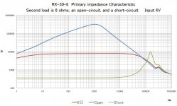
Regarding the bandwidth issue, output transformers (especially series feed single ended transformers) have a boundary where they can operate. On the lower end, the minimum load you can reflect is approximately the DCR of the primary winding. On the other end, the highest impedance you can reflect is controlled by the parasitic elements of the transformer. I've attached an image showing a typical measurement reflecting this issue.
100mW into 300 ohms is 5.4V.
In terms of "conventional" tube amplifiers, this is available from the 8 ohm tap of a 2-3 watt tube amp. You could stretch and get this from a 16 ohm winding on a 1.5W amp.
If you take a 2-3W amp and have a 300 ohm winding made, you will have 2000-3000mW of power at the headphone output, which isn't useful. With the lower step-down ratio, you will also have a much noisier amp.
Regarding the bandwidth issue, output transformers (especially series feed single ended transformers) have a boundary where they can operate. On the lower end, the minimum load you can reflect is approximately the DCR of the primary winding. On the other end, the highest impedance you can reflect is controlled by the parasitic elements of the transformer. I've attached an image showing a typical measurement reflecting this issue.
Attachments
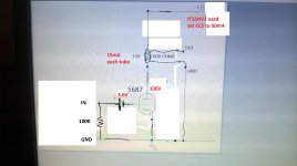
Can you draw up a schematic (a photo of a hand drawing is totally OK) of what you have built, just so we can get a complete picture?
- Home
- Amplifiers
- Tubes / Valves
- Changing triode load