Hey all,
Its been a while since I've posted here... Life, marriage, moves, dogs, kids, jobs, kid with cancer, covid.... Anyhow, all is well bow and I'm interested in getting my 2 channel system back up and running.
I have ProAc D15s at 88db. I built a 12b4a linestage that was feeding an AR VT100 MKIIs. Sold the VT100 and was using a PP EL34 kit for a while but that is now gone. I have a 10 year old breadboard of a 6sn7>300B>845 but I don't want to work on that now as the voltage scared me back then, and well, its been a while since I've used the solder iron.
What I would like to build is a solid, clean amp to power the ProACs. 35 Watts is decent but for big transitions, having more headroom would be ideal.
As I mentioned its been a while since I've been here. My old brain would tell me 6550 in PPP? What are other options that would suit my needs? What's changed in the past 8 years?
I listen to classic rock, piano, bluegrass, jazz etc.
All help and guidance is appreciated.
Many Thanks,
Bryan
PP KT88/6550 "finals" get you 60+ WPC. Mullard style topology is "idiot resistant" and that's what I'd use. The H/K Cit. 5, with its high gm small signal types, is a superior implementation of Mullard style and (IMO) is an excellent place to start.
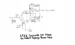
12BY7s are getting scarce. A 6922 cascode is provided as a substitute high gm voltage amplifier. CCS loading the LTP tail and, perhaps, an ECC99 as the LTP are incremental improvements of something pretty darned good in its original form.
12BY7s are getting scarce. A 6922 cascode is provided as a substitute high gm voltage amplifier. CCS loading the LTP tail and, perhaps, an ECC99 as the LTP are incremental improvements of something pretty darned good in its original form.
Attachments
100k grid resistors and fixed bias.
Be sure to use KT88 outputs or 7581.
Do not use 6550 outputs (50k max grid resistors for fixed bias).
I found out the hard way, red-plated a 6550 because of fixed bias and higher than 50k grid resistor.
Just sayin'
Be sure to use KT88 outputs or 7581.
Do not use 6550 outputs (50k max grid resistors for fixed bias).
I found out the hard way, red-plated a 6550 because of fixed bias and higher than 50k grid resistor.
Just sayin'
Thanks Eli and 6A3,
Seems like KT88 in PP will fit the bill, and is probably a smart, "easy" and reliable enough option for my needs. I like the circuit attached, thought the cascode IP stage is a bit hard to read.. I'll study up on the topology and see what I can learn before coming back with lots of questions.
For the iron, knowing I want "great sound", what would you suggest?
Secondly, for the rectification, is there any advantage going with SS vs tube as in the above circuit? All amps I've build in the past have been tube rectified. Just curious.
Thanks!
Bryan
KT88. SS tends to result in less variation of HT with large amplitude signals this affects to gain of the output stage. If its hi-fi then you want the HT to remain reasonably constant. I've not built with valve rectification but I think they look nice. The SS may need a soft start to stop it taking a big chunk out of the mains when you turn it on. I tend to use a bigger main HT cap say 1000uF. Smaller values will cause the 120Hz to modulate the output signal if it is large.
Last edited:
Secondly, for the rectification, is there any advantage going with SS vs tube as in the above circuit? All amps I've build in the past have been tube rectified. Just curious.
These days, no good reason remains for employing vacuum rectifiers in a power amp. High PIV Schottky diodes are as quiet as tube diodes and they don't "sag", when the draw increases. Tube rectifiers with cathode sleeves are automatically "soft" starting. Some effort is required to "soften" SS diode start, but a simple CL-140 inrush current limiter between rectifier and filter is good enough, when "fixed" bias is employed.
100k grid resistors and fixed bias.
Be sure to use KT88 outputs or 7581.
Do not use 6550 outputs (50k max grid resistors for fixed bias).
I found out the hard way, red-plated a 6550 because of fixed bias and higher than 50k grid resistor.
Just sayin'
That conundrum is easily disposed of. 😉 Employ combination bias. "Stand" cathodes on 100 Ω/470 μF. RC bias networks. The bulk of the total bias voltage comes from a C- supply, but enough self generated bias is present to prevent runaway.
Notice the convenient "idle" current test point. The technique also allows for some simplification/cost control. A single RC network per PP pair will automatically correct for minor differences in cathode current, while only 1 bias trim pot. is used.
For the iron, knowing I want "great sound", what would you suggest?
Magnetics are costly and represent a major part of the cash outlay in building a tube power amp.
Mullard style circuitry is known to deliver satisfactory results, when "iron" that is not the very best is employed. With that in mind, I suggest you look at Edcor's model CXPP100-3.3K for a KT88/6550 build. Solid, if unspectacular, performance is what you get. Edcor is an excellent value.
That's an interesting idea have both -ve grid bias and some cathode bias. I prefer the 6550 as in my opinion its more linear in ultra linear connection than the KT88. Your no in ultra-linear so I don't know.
I know Mr Summer says he has blown up because of 100k bias. He is correct it is out of spec. However I have seen many production amps use 100k with 6550. When I have a moment I will try and measure the grid current at normal operation and red plated on a modern 6550EH. I will report back the results when I try.
I've used hammond before with good results. Maybe 1650NA I think you have about 65W per channel at a guess.
Last edited:
Eli,
If spectacular was the goal, what iron would you suggest and your your choice of circuit remain the same?
If spectacular was the goal, what iron would you suggest and your your choice of circuit remain the same?
Well I of course would go ultra-linear. However that will change the gain and you will have to alter the NFB. You would be over the limit for the 6550 on screen voltage so you would need KT88. The NFB may need adjustment for different transformers.
Its moving away from that nice design you started with which has all the bits designed to certain performance level. I think both recommendations for transformer are 'good enough'
Its moving away from that nice design you started with which has all the bits designed to certain performance level. I think both recommendations for transformer are 'good enough'
Eli,
If spectacular was the goal, what iron would you suggest and your your choice of circuit remain the same?
Truly spectacular requires "iron" that's not available for a new build. Among the very best amps, ever, is the Harman-Kardon Citation II. The Freed magnetics in the "Deuce" are pure gold, but you have to cannibalize an amp to get them. That's (IMO) vandalism. 😡 Now, a project of acquisition and refurbishment of a H/K Cit. 2, ala Jim McShane, has my complete support. No, you can't have my "Deuce". 😀 I'll part ways with it, when "dirt nap" time comes.
The Cit. 5 is the "little brother" of the Cit. 2 and doesn't bring the rear up by much. McShane is on record stating the "Five" will slightly out image a "Deuce", but (all around) the Cit. 2 is the better amp.
Prepare to spend BIG $ for magnetics truly better than those made by Edcor. Potential winders can be suggested, if your pockets are deep enough.
Ultra-linear (UL) mode can be good and the previously linked Edcor model comes with UL taps. Full pentode mode can be every bit as satisfactory as UL, when g2 B+ is regulated at a fraction of anode B+. Regulating g2 B+ maximizes open loop linearity. In particular, the amount of highly irritating intermodulation distortion (IMD) is held down.
In addition to Mullard style, Williamson style topology is also "classic". Williamson style is vulnerable to low frequency instability ("motorboating") and is less forgiving of O/P "iron" foibles. JMO, a Mullard style project has a better chance of ending well. "Idiot resistant" is good.
Thanks again guys. Seems I have lots to digest.
As it’s been a while since I’ve slung solder it’s probably a good idea to keep things relatively straight forward and not too expensive. Once I’m a bit more practiced I can tackle something more elaborate.
So, now I’m thinking KT88 with the 6922 and ecc99 with the Output in UL assuming the regulation strategies are not overly complex.
What would one do for regulation of g2 and the 6922 for that matter?
Thanks for getting my brain off lock down and cranky kids!!
Bryan
If I remember correctly, the 6550 was an original Tung Sol (not some re-branded, and not some modern manufacturer).
The plate was at 451V, the screen at 446V.
The cathode current was 50mA.
The plate plus screen dissipation was just under 22.55 Watts.
Easy quiescent state for a 6550.
But, the high resistance G1 grid resistor caused it to red-plate.
50k fixed it.
An EL34 worked perfectly with as high as 270k in that same amp for 100s of hours (pin 1 connected to pin 8, suppressor grid, G3 comes out at pin 1, and is not internally connected to the cathode).
The EL34 never skipped a beat.
Then the amp was torn apart, and re-configured into a completely different circuit topology.
As to UL operation, the most common UL circuits do not regulate the screens.
The UL screen voltage is usually dependent on the following:
B+ Voltage;
DCR from the OPT center tap to the UL tap;
Voltage drop due to the Plate current plus screen current through that DCR;
And . . .
The resistor from the UL tap to the screen (usually 100 Ohms, if present at all).
Note:
In UL operation, the screen voltage swings all over the place, as a percentage of the plate voltage swing.
40%, or whatever.
I recently did a single ended KT66 with 50% UL tap.
I have seen references of UL taps from 23% to 75% in a major tube application book.
The 100% UL tap is otherwise called . . . Triode Wired.
If you want to regulate the screen voltage, G2, then use the KT88 or 6550 as a Beam Power Tetrode,
not for UL.
Last edited:
So, now I’m thinking KT88 with the 6922 and ecc99 with the Output in UL assuming the regulation strategies are not overly complex.
Here are a couple of old threads that may have some value. This may be the time to wade thru them.😉
Mullard 5-20 KT88 PP blocks!
OPUS 5.0 A Modern Mullard
jeff
Thanks again guys. Seems I have lots to digest.
As it’s been a while since I’ve slung solder it’s probably a good idea to keep things relatively straight forward and not too expensive. Once I’m a bit more practiced I can tackle something more elaborate.
So, now I’m thinking KT88 with the 6922 and ecc99 with the Output in UL assuming the regulation strategies are not overly complex.
What would one do for regulation of g2 and the 6922 for that matter?
Thanks for getting my brain off lock down and cranky kids!!
Bryan
Mike Maida wrote a seminal paper on high voltage regulation. Read it. A very nice recent implementation of Maida's concept can be found here. Tom C. is a member here at DIY Audio and a lengthy thread discussing his work can be found in the archives. Tom's PCB will easily feed 4X KT88 screen grids.
A visually appealing g2 regulation strategy is stacks of gas discharge regulator tubes. They will consume valuable chassis space and come in Octal and 7 pin mini packages. FWIW, I favor this approach in combination with "12" W. types (not big, honking, KT88s) where both voltage and current requirements for g2 B+ are modest.
Power supply rejection ratio (PSRR) is essentially non-existent in cascodes, which is why I call for regulated B+. However, VERY well filtered "juice" is an alternative. Stopping a buzz at 2X the power line frequency is the target of these machinations.
One major difference between Solid State diodes for B+ circuit,
versus Tube Rectifier for the B+ circuit . . .
Is the transformer secondary voltage you select.
If you already have a power transformer that has the correct secondary voltage for a tube rectifier, the only way to make it produce the same B+ voltage with solid state rectifiers is to use dropping resistor(s) to drop enough voltage to set the B+ at the same level as it was when the tube rectifier was in the circuit.
And that makes the B+ have no better regulation with solid state rectifiers than with the tube rectifier.
And, the resistors heat up just as much with the solid state rectifiers as the tube plates heated up.
The only heat savings are the 5V rectifier secondary, and the tube filament.
If you want to use solid state rectifiers, then start from scratch, and pick a transformer secondary that gives you the B+ voltage you want, without having to use the large series resistor(s).
And then, and only then, the solid state rectifier B+ will be stiffer than the tube rectified B+.
Using a regulator to stiffen the B+ is a completely different matter than the above.
But of course, it adds complexity.
Last edited:
You will not need line stage gain, when modern digital signal sources are employed. A pair of log. taper pots. at the I/Ps give you instant "integrated" amp and that favors a stereoblock.
Monoblocks are easier to handle, weight wise, and allow for short speaker cabling runs. Against those positives, increased costs enter the picture.
It's a "classic" situation of selecting the compromise you will "live" with.
Monoblocks are easier to handle, weight wise, and allow for short speaker cabling runs. Against those positives, increased costs enter the picture.
It's a "classic" situation of selecting the compromise you will "live" with.
- Home
- Amplifiers
- Tubes / Valves
- Amp Project for my 88db ProAcs