It looks like you may have installed both the R7' trimmer and R7 fixed resistors. That will make it difficult to set the offset correctly. Remove the fixed resistor, and the trimmer should let you adjust the offset very close to zero.
There is no position for a fixed R7 when VR7 is fitted.
As I've already stated; I can adjust the DC offset, I can get it to swing from virtually rail to rail.
It is incredibly sensitive around 0V. When set at 0V and left for 10 mins it will wander sometimes quite dramatically.
It is incredibly sensitive around 0V. When set at 0V and left for 10 mins it will wander sometimes quite dramatically.
So, if you can swing it to either side of 0V0 - then the pot value is likely fine. Make sense?
Does it constantly drift in one direction? i.e. if you adjust the pot so the offset reads around -0V1 does it wander to +0V to +1V and on up, or does it wander to -0V2 and onward in the other direction. I asked what you meant by "dramatically" - units help.
1) You said a slight turn of the pot made the value change quite a bit ~10V as I recall. Is that still the case?
2) You've said it's "sensitive" - which I think ties to above. Is that still the case?
If one or two are true - Do this. Whatever value it's at right now - type it (with polarity).
Then turn the pot one full turn in the direction of your choosing and write the new value. If it's wandering ballpark it.
Then - do this exactly, please.
Get it as close to 0V0 as you can. Leave it for about 10 mins. Report the value and include the polarity. If it's wandering, tell us by how much.
Examples that will help
- Was centered around 0V0 +- 10mV, but drifted to +1V0 and is still climbing.
- Stayed dead locked at 0V02, then drifted to -0V52 and is steady
- Was centered around 0V0 +-10mV, but now it's less stable and it's 0V0 +-1V
BTW - I know the other reply was for TA, but where'd ya put the jumper then? 😀
Edited to add - Sorry ... early morning, that was the jumper for the bias pot. We've moved on to offset.
I can get it to stabilise within +/- 2.5V.
If I set it to say +100mV then it drifts up to +ve
If I set it to say -100mV then it drifts down to -ve
I am veering toward the 10T pot just not having the resolution required.
It's also possible that my e-bay 10T pot may not be of very good quality ?
If I set it to say +100mV then it drifts up to +ve
If I set it to say -100mV then it drifts down to -ve
I am veering toward the 10T pot just not having the resolution required.
It's also possible that my e-bay 10T pot may not be of very good quality ?
Last edited:
Yep - I should have looked at the schematic to see that R30 was what he was referring to. I own that.
KatieandDad - yank R30. Jumper it. Carry on.
TA - You da man, too!
KatieandDad - yank R30. Jumper it. Carry on.
TA - You da man, too!
If R30 is fairly small it shouldn't have an effect and gives a way of measuring the
total current coming out of Q2 and going to the LTP Q1A/Q1B (especially if one
uses an R8 pot and have been playing with it.)
total current coming out of Q2 and going to the LTP Q1A/Q1B (especially if one
uses an R8 pot and have been playing with it.)
If R30 is fairly small
Yep I’d keep it if it’s small.
Edit: Per BOM <100R is okay.
Last edited:
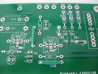
I can't see the logos on the PCB now all the components are installed. Can someone show me where R30 is. I think it is 1R0.
My fault... again.... I should have checked the value before suggesting to just pull and jumper it. I'll let brighter minds continue. 😀
It's also possible that my e-bay 10T pot may not be of very good quality ?
If you have a set of fixed resistors handy, you can always substitute a fixed resistor having the same value as the pot when set to 0V on the output and see what happens.
It may be a good idea anyway:
I always recommend replacing trimpot with fixed resistors
If you can be patient with me the new 50T pots should be here later this week.
I'm very concerned about attaching speakers at the moment with the unstable DC output.
My attempt at an F5 completely fried my B&W 683s.
This design has output protection which triggers at 1V.
I'm very concerned about attaching speakers at the moment with the unstable DC output.
My attempt at an F5 completely fried my B&W 683s.
This design has output protection which triggers at 1V.
These symptoms indicate a more fundamental problem with the circuit than adjustment of the pot. With a delicate touch, offset could be set with a three turn pot, and it would remain stable once set. (I use 3-turn pots in my B1 Korg.) Having the offset slam up against one rail or another indicates a circuit fault, not an adjustment problem.I can get it to stabilise within +/- 2.5V.
If I set it to say +100mV then it drifts up to +ve
If I set it to say -100mV then it drifts down to -ve
I am veering toward the 10T pot just not having the resolution required.
It's also possible that my e-bay 10T pot may not be of very good quality ?
Next step:
Replace R30 with a 100 Ohm resistor. This will make it easy to determine the current flowing through the tail of the differential pair. Yes, the tail is on top with the P-channel JFets. Maintain a reading of the voltage across R30 while you are attempting to adjust the offset. Watch the reading as the offset drifts away from where you left it. If this value changes, then the fault is with one or more of the components above R30. If it doesn't change, then one or both of the P-channel parts are at fault.
I'm assuming that the power Mosfets are functioning correctly. You might try pulling Q3, though, to see if there is a problem with this sub-circuit.
- Home
- Amplifiers
- Pass Labs
- Aleph J Setting DC Offset