In RF applications chokes are operated either with high bias and very low flux swing (filters) or with no bias and moderate flux swing (tuned stages). Only in SMPS chokes are operated with high bias and high flux swing (power conversion). +/-10A on top of 40A? What kind of output power would that be on RF? In RF 200W is already a lot of power hahaha
Yes the currents are very high in such resonant converters (10's of A)* the trick is to confine the current to high Q LC tanks. Quality factors exceeded 1000 in the work I was doing so losses are negligible. Designing class-E stuff for power transfer is a bit different to RF usage as your aiming for maximum efficiency rather than operating into 50 ohms. If you used impedance matching between everything your efficiency is poor due to losses in the matching network and that the inverter and rectifier are not operating optimally. So you do things like have a complex output impedance driving your rectifier, which needs to be taken into account in the design of it.
*Saturation is not usually a problem due to the low permeability of the cores used
*Saturation is not usually a problem due to the low permeability of the cores used
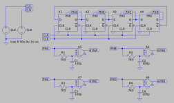
Umm-mm .. This may be an un-useful aside, but your blanking generator in post #14 will probably require a synchronous counter -- rather than the ripple-carry illustrated -- if you're to avoid nasty decoding spikes in the Blank signal.
Or you can get 4 (or more) very reliable, glitch-free phases from an HC4017 or similar.
Cheeez - you's guys can get 3 kilowatts out of a standard residential outlet!? I'm so jealous .. 😉
Regards
Or you can get 4 (or more) very reliable, glitch-free phases from an HC4017 or similar.
Cheeez - you's guys can get 3 kilowatts out of a standard residential outlet!? I'm so jealous .. 😉
Regards
Umm-mm .. Cheeez - you's guys can get 3 kilowatts out of a standard residential outlet!? I'm so jealous .. 😉
TMI: Every time I pee or poop I get 5.5KW out of a "120V 20A" circuit. My well-pump has a 44 Amp start surge (and I have 125V at the pole). The surge is <1/10 second, but how long is an audio peak?
Here is 3 loud-ish seconds from a recent job. Normalized exactly. In these 3 seconds:
Peak Amplitude: 0 dB
Maximum RMS Power: -7.52 dB
Average RMS Power: -18.52 dB
1/10th second is highlighted. In this 0.1 second:
Peak Amplitude: 0 dB
Average RMS Power: -10.64 dB
The tripping time for a circuit breaker at 10X overload (200A on 20A breaker) is about 3 seconds. So my well-pump's 44A 0.1s start-surge never tickles my 20A breaker, and a 0.1 sec 1.25X audio demand is "nothing" since it isn't sustained. (If it is, speakers and ears will bleed.)
Attachments
Thanks PRR! Always appreciate actual hard data!
Can we assume that job wasn't using much in the way of compression or limiting? Just curious ..
Actually, I think I'm just still good and cranky over the storm here about a year ago now. A branch from a couple-doors-up neighbor's tree took out our trunk by snapping off three poles, including *our's* with the transformer .. and when it was *restored*, the other two phases (of, is it 4700V? that's the next voltage up) that used to stop at *our pole* WEREN'T THERE! Sorry -- well off topic now ..
Anyway, thanks for refreshing my (typically warped) perspective.😉
Umm-mm .. This may be an un-useful aside, but your blanking generator in post #14 will probably require a synchronous counter -- rather than the ripple-carry illustrated -- if you're to avoid nasty decoding spikes in the Blank signal.
Or you can get 4 (or more) very reliable, glitch-free phases from an HC4017 or similar.
Cheeez - you's guys can get 3 kilowatts out of a standard residential outlet!? I'm so jealous .. 😉
Regards
Thanks! clearly far too much FPGA work on the mind, have forgotten what I'm doing with logic chips.
we get 230*13A nominally but usually the voltage is 240V so 3.12 kW. You can only pull 20A from a double socket though and ring mains are often only 30A. For the house fuse 60A is common but it can be up to 100A. I have lived in a house that had 125A 3 phase but it used to be a residential care home. 3 phase is very common in light industrial units and above but getting more than 100A feeder can be (unexpectedly) expensive, when upgrading the power company standard contact puts any unexpected expenses on you. I once ran a big stack of powersoft and LG amps through a single 5A fuse, the fuse only blew (in under half a second) during almost clipping bass sine wave sweeps, loud music wasn't enough.
As you appear to have surmised your original thought about ground current sensing kind of falls apart for your interleaved multiphase case. You end up having to sense at rail and have suggested some of those GMR things.
Going completely off the rail there are things called current shunt monitors...
https://www.farnell.com/datasheets/706593.pdf
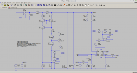
Also suggests the use of a cascode to allow operation at higher voltages or once again madness enters the fray and you might consider the attached piccy and .asc
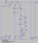
Q1, Q2 and Q3 form a Wilson current mirror degenerated with R1 and R2. Current nominally set with R3 and R4 to 2mA. They also provide bias to cascode Q4. This is to avoid exceeding the Vce ratings of the transistors.
For zero current in RSNS the same 2mA flows down each leg. Voltage across R6 is balanced by the opamp placing the same current through R7, same value resistors. The current imbalance is 1mA/V across RSNS so the output sensitivity is 100mV/A at the output of the opamp, SNS.
It appears to work but as is usually the case with such mad ideas there is probably a gotcha I have not thought of.
Going completely off the rail there are things called current shunt monitors...
https://www.farnell.com/datasheets/706593.pdf
Also suggests the use of a cascode to allow operation at higher voltages or once again madness enters the fray and you might consider the attached piccy and .asc
Q1, Q2 and Q3 form a Wilson current mirror degenerated with R1 and R2. Current nominally set with R3 and R4 to 2mA. They also provide bias to cascode Q4. This is to avoid exceeding the Vce ratings of the transistors.
For zero current in RSNS the same 2mA flows down each leg. Voltage across R6 is balanced by the opamp placing the same current through R7, same value resistors. The current imbalance is 1mA/V across RSNS so the output sensitivity is 100mV/A at the output of the opamp, SNS.
It appears to work but as is usually the case with such mad ideas there is probably a gotcha I have not thought of.
Attachments
AD8212 looks cool, the issue I see with your circuit as it is, is that the output amplitude is sensitive to vout. could always be fixed with more transistors though.
One issue I have just thought of is that if my switching frequency is 200kHz and my current sensors are -3dB@1MHz the delay in the current sensor may be significant.
One issue I have just thought of is that if my switching frequency is 200kHz and my current sensors are -3dB@1MHz the delay in the current sensor may be significant.
It's a bit cunning. The bias level, 2mA, is sensitive to Vout but being a current mirror changes in Vout affect both legs equally and the differential result is zero. There may be a minor gain error, some temperature effects and as you have hinted bandwidth could be an issue. The model waveforms suggest a fairly faithful reproduction of the current signal.
It's always tempting to go as fast as possible but do you really really need to. Peak current mode control with slope compensation degenerates to average current mode control with slope matching. The sums say your maximum loop crossover frequency will be Fs/2PiD, there is a trick in there.
However 100KHz/Leg gives you an effective Fs of 400KHz and your loop will/might have to crossover down below 100KHz. That's still streets ahead of what your big boom box will be trying to reproduce. In terms of the additional phase shift introduced by the sensor... yes bear it in mind but it's not likely to hurt.
Here's a hack at your synchronisation. As I say I would use average current mode control based around something like the UCC35705 PWM IC to control each phase and then tie things together in the rest of the control.
...
Attachments
I have another engineer friend on board now so I'm thinking of doing the control using a C2000 series MCU (I have done digital controllers before I just don't like programing) (well mainly development environments and all their bugs). I was getting quite concerned about the cost and size of all the components required for a 4 phase controller! (although UCC35705 would seem to reduce this a bit).
When I had a play around with your current sense circuit in spice I changed the bus voltage (to 200v from 400V) and observed a change in output voltage amplitude (1Vpp to 500mVpp), not an issue normally but my converter will potentially have an output voltage of 0V (if there is a hard short) . (although potentially advantageous as the optimal slope will also change...)
Your comments about the required bandwidth make sense, I suspect as I'm going to put a large capacitor bank on the output my required bandwidth will actually be very modest. I found the attached document on average current mode control.
Attachments
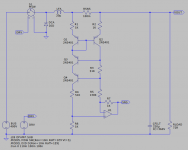
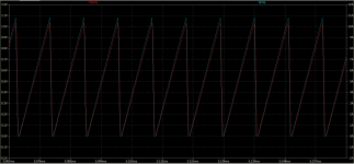
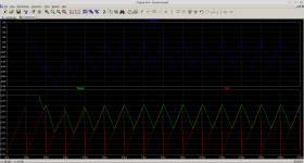
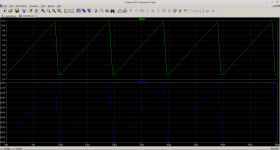
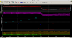
The circuit is just a demonstration. As such the DRV duty cycle is fixed at 90%. Being a buck convertor then VOUT = D.VIN, D being the duty cycle. For 400V in the output would be 360V. A 72R load would draw an average current of 5A. In the model the filter inductor was set to be on the verge of discontinuous operation with a 5A load. It would therefore be a 10A peak triangle wave with the average being 5A.
Reducing VIN to 200V means the new value for VOUT would be about 180V which with a 72R load would be an average output current of 2.5A. The circuit remains on the verge of discontinuous operation so you get a 5A peak triangle wave with the average being 2.5A.
1Vpp -> 500mVpp
The circuit is doing the right sort of thing. In terms of headroom the limit is going to be loss across R4. If you use a 400V Vceo transistor for the cascode, MPSA94, then you can omit R4 and it will operate down to mumble volts where mumble would be about 5V. I used what was available in LTSpice so was limited to 150V Vceo.
The Lloyd Dixon Application note is the one. 🙂
I'm trying to knock together a UCC35705 model in LTSpice. Piccy is a first thrown together guess regulating 10A.
...
Attachments
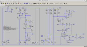
You wanted more transistors.
I procrastinated and messed about with the current sense circuit a little bit. New version includes MPSA44/94 high voltage transistors and a floating two terminal current bias network comprising Q4-Q7. This one should operate down to about 7V at VOUT.
...
I procrastinated and messed about with the current sense circuit a little bit. New version includes MPSA44/94 high voltage transistors and a floating two terminal current bias network comprising Q4-Q7. This one should operate down to about 7V at VOUT.
...
Attachments
Wasn't it this thread where somebody mentioned the app note "TI Designs: TIDA-00779"?
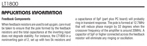
Tables 2 through 11 (pages 10 through 15) show some pretty stellar performance -- especially for an under USD $2, SO-8 part that is only trying to control PFC! And if you didn't need the full international 85 - 270VAC tolerance, the supporting parts would probably be even cheaper.
Then, since you don't need isolation, you'd have your pick of just about any topology for the conversion from 393VDC to whatever rail(s) you want.
Just a thought .. Cheers
edit: Apologies if MorbidFractal's recent posts already covered some of this 😱 haven't finished studying those yet.
Last edited:

You wanted more transistors.
I procrastinated and messed about with the current sense circuit a little bit. New version includes MPSA44/94 high voltage transistors and a floating two terminal current bias network comprising Q4-Q7. This one should operate down to about 7V at VOUT.
...
Looking good, it occurred to be my earlier comment about voltage sensitivity was silly, of course the output current changed. Operating down to 7V is great, if the output has sagged that much there is a fault and its time to turn the whole supply off.
I have been fiddling around with your circuit and found a potential issue in that at low currents the stability appears not great (gain peaking). This is caused by operating the OPAMP near the supply rails, this is easy to solve though by using a LM2776 to generate a negative supply rail. I would also suggest the use of LT1805 instead of LT1800 as its got similar specs but is a quad OPAMP rather than a single so greatly reduces the cost of a quad phase converter.
Attachments
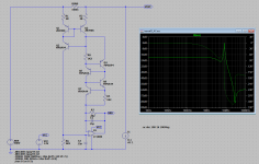
It's not strictly a valid analysis because you have removed the output filter capacitor and the input inductor. Bear in mind that the circuit places the sense resistor in series with the inductor, the switch and catch diode are on the other side, so that it truly measures total inductor current. At HF the capacitor on its own will blow away your pesky little current sink.
The data sheet for the LT1800 does mention the possibility of instability due to board parasitics and such behaviour does appear to manifest itself in the Spice model. In part that's why I've slugged the circuit with the two capacitors around the amplifier. There is however a possibly evil additional feedback loop round my bucket of transistors that could benefit from fitting of the random capacitor.
...
Attachments
And..... Getting well ahead of myself again.
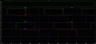
We have to sort out the peak limit in the PWM controller and that means you have to apply the thing that always causes, not just you, problems known as slope compensation. Again I've hacked an answer which means I threw something in and adjusted things to work.
In a similar vein I've tagged on a voltage error amplifier. Again I've waved my hands at it and cobbled together something that works. There are some underlying reasons to this. Of course I should settle down and write some proper words to explain just where I think my head is at.
This time I've just included the .asc file. You should have the previous/additional bits from the last .zip file.
...
Attachments
It's not strictly a valid analysis because you have removed the output filter capacitor and the input inductor. Bear in mind that the circuit places the sense resistor in series with the inductor, the switch and catch diode are on the other side, so that it truly measures total inductor current. At HF the capacitor on its own will blow away your pesky little current sink.
...
I think the simulation is valid as this is a current sensor so I'm measuring its transfer function. The instability is showing up because near the supply rails the OPAMP performance becomes crappy due to lack of gain inside it. In practice probably not a problem as the instability would be damped as soon as the OPAMP output moved away from the rails, so worst case a bit noisy at low current. Which considering at low current current mode control is doing nothing thats not an issue.
I have been thinking about MOSFETS and found that Si MOSFETS are as crappy as I remember due to the reverse recovery. Was looking at 18W per FET without any current flow just due to switching at 200 kHz.
GS-065-011-1-L from GaN Systems seems to reduce that idle loss down to 1.4W or so. It might be optimal to use a larger device though, I need to have a look at gate drives to do more realistic simulations as I have been out the game for a couple of years so don't know the current best options:
https://www.silabs.com/documents/public/data-sheets/Si827x.pdf
https://www.infineon.com/dgdl/Infin...N.pdf?fileId=5546d462636cc8fb0163b08fd9203057
Last edited:
- Home
- Amplifiers
- Power Supplies
- Energy storage in non isolated amplifier PFC stage