Hey all,
I'm finally going to be finishing my SSE build. I'm pretty excited to finally be putting this together. I bought the board back around 2012, bought various parts for it here and there and shelved it for a long time. Finally got around to soldering the board and getting the final components. Just wanted to say thank you to George and everyone on here for their insight. I don't really post at all but I am always lurking around the Tube Lab threads.
Here's the build:
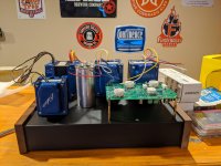
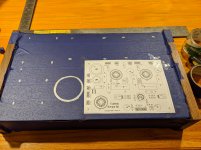
Picked up a Hammond chassis from Digikey a while back, glad I went with this size as the iron I got from Edcor are huuuuge. I need to finish up a few things on the board yet. I got the wrong coupling caps installed somehow, I missed the correct value and put in .045 auricaps.
I am using all Edcor power,output and choke for the build.
I ended up getting the XPWR035 trans and the CXSE25-8-5k output transformers and a CXC125-10-200ma choke.
For tubes I picked up Tung Sol 6L6GC STR, Tung Sol 5AR4, and 12AT7 Electro Harmonix. At some point I may pick up some others but those I felt were reasonably priced to start with.
As always any input or questions are welcome!
Cheers!
Later this week I'll get to cutting the chasis and wiring this thing up! I can't wait!
I'm finally going to be finishing my SSE build. I'm pretty excited to finally be putting this together. I bought the board back around 2012, bought various parts for it here and there and shelved it for a long time. Finally got around to soldering the board and getting the final components. Just wanted to say thank you to George and everyone on here for their insight. I don't really post at all but I am always lurking around the Tube Lab threads.
Here's the build:
Picked up a Hammond chassis from Digikey a while back, glad I went with this size as the iron I got from Edcor are huuuuge. I need to finish up a few things on the board yet. I got the wrong coupling caps installed somehow, I missed the correct value and put in .045 auricaps.
I am using all Edcor power,output and choke for the build.
I ended up getting the XPWR035 trans and the CXSE25-8-5k output transformers and a CXC125-10-200ma choke.
For tubes I picked up Tung Sol 6L6GC STR, Tung Sol 5AR4, and 12AT7 Electro Harmonix. At some point I may pick up some others but those I felt were reasonably priced to start with.
As always any input or questions are welcome!
Cheers!
Later this week I'll get to cutting the chasis and wiring this thing up! I can't wait!
Attachments
Looking great, man! I'll pull up a chair and watch the rest of this build. Please continue posting!
By the way, I just started mine today. The resistors are done. Waiting on delivery of the tube sockets... Fun stuff!
By the way, I just started mine today. The resistors are done. Waiting on delivery of the tube sockets... Fun stuff!
Last edited:
Hey,
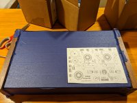
Cogitech hopefully your build doesn't take you as long as mine did. Got the chasis pretty much laid out today and am ready to start cutting and drilling holes. Picked up a cheap step drill kit from Harbor Freight and a rubber gromet kit to place in the holes for the opt/trans wiring. That will be my plan for tomorrow.
I noticed today I ordered the wrong IEC receptical, so I ordered a new one that is EMI with the on/off switch and fuse integrated into one. Can't see filtering the main supply doing any bad, I know certain folks feel differently.
06AK2D Delta Electronics | Connectors, Interconnects | DigiKey
Heres the chasis ready to drill! Should have it done later this week and start testing it out.
Attachments
I hope to be done mine in a few months, but realistically it could take longer. I have made a commitment to myself to DO IT RIGHT, which means take my time with every step and really think things through. Also, I don't have the cash to spend on all the components at once, so as money and time allows I will work away at it.
Yours is coming along nicely. Looking forward to seeing it all put together.
Yours is coming along nicely. Looking forward to seeing it all put together.
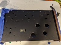
Pretty much got the chassis all drilled out and everything test fit for install. I hope to start wiring up by Friday and finish it up this weekend.
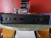
I was drilling my holes for the RCA and speaker jacks and started to second guess how I should install them, so I isolated them from the chassis, then I started thinking they are going to be grounded to the chassis anyway so there really isnt much of a benefit in doing so? Too late now, my holes are already drilled! I think im to paranoid about interference.
I was drilling my holes for the RCA and speaker jacks and started to second guess how I should install them, so I isolated them from the chassis, then I started thinking they are going to be grounded to the chassis anyway so there really isnt much of a benefit in doing so? Too late now, my holes are already drilled! I think im to paranoid about interference.
Last edited:
Looking forward to seeing the final product!
I'm not one to be giving any advice on grounding, so I won't.
I'm not one to be giving any advice on grounding, so I won't.
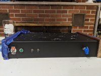
Everything is drilled and ready for install on the chassis. I accidentally drilled the wrong holes for my OPT/trans wires so I have a extra holes. I guess this way I can mess around with orientation. I also forgot I was integrating the power switch with the new IEC receptical and put one on the front as well. I so l'll use this for my standby switch.
I'm only installing the stand by and rectifier switch at the moment.
Not too much of a hassle. My step bit got stuck cutting out the tube/octal sockets so I'll have to hammer those back down smooth before install. IEC socket got a little crooked cutting the hole..down the road if it bothers my I'll pull it out and cut a black lexan sleeve/trim piece for it to level it out.
Wiring comes tomorrow!
I'll post some pictures later having issues at the moment.
Just noticed this now. Good progress!
I wish I had all the parts I need to continue my build. Hopefully I'll be able to post some progress in a few weeks.
Oh - one thing I do know about grounding is that those binding posts need to be isolated/insulated from the chassis. You probably know this already, but just in case...
I wish I had all the parts I need to continue my build. Hopefully I'll be able to post some progress in a few weeks.
Oh - one thing I do know about grounding is that those binding posts need to be isolated/insulated from the chassis. You probably know this already, but just in case...
Good morning! Just having my morning coffee and looking on Tubelab.com, then remembered you talking about a standby switch.
Not sure if you are aware, but George strongly recommends against a standby switch now. Maybe you can put an LED in that hole. One in a housing of the right size. Or, put a switch of some sort in there for looks (not connected) and then use that spot for a CFB or UL/triode switch at a later date. You can use that dummy switch to see if your audiophile friends are full of sh!t. Tell them it is the rectification switch and then say "hear the difference?"
"Notice!
The assembly instructions for the SSE show the optional installation of a standby switch. There have been a few instances of blown diodes associated with the use of a standby switch. Investigation has revealed that some power transformers (particularly Hammonds) can generate a 2500 volt spike when the standby switch is operated. It is recommended that the standby switch be omitted from new builds, and not used on existing amps. The instructions will be changed as soon as I can get to it."
Last edited:
Hey Cogitech,
Thanks for all the input. I've been obsessing with the grounding of the amp. I'll stick to what George has on his diagrams and make sure I only have one ground path to the PCB, and that the input Jack's are isolated.
Somehow I missed not using a standby switch! Thanks for the heads up. I'm sure I could come up with a fail safe for the voltage spike but, for now will leave it out. Like you said maybe I can use the switch and have some fun with friends...I know one in particular I'm sure I could get to fall for it!
Off to get a heat gun and wire it up! If the wife doesn't bother me I should have this humming by late afternoon!
Omitting the standby switch is a good idea. They're difficult to implement correctly to begin with, and besides there's really no good reason to use one in this amp. Just throw in a CL-140 inrush current limiter (or whatever George recommends) on the hot lead between the fuse and power transformer primary and call it good. Just keep it away from anything flammable.
Your time is much better spent working on good grounding.
Cogitech, I like the idea of the "phoolery" switch, heh, heh...
Your time is much better spent working on good grounding.
Cogitech, I like the idea of the "phoolery" switch, heh, heh...
Last edited:
If the wife doesn't bother me I should have this humming by late afternoon!
Ha! Good luck with that, and remember - the last thing you want to do is get that thing humming! 🙂 Make it SING!
Omitting the standby switch is a good idea. They're difficult to implement correctly to begin with, and besides there's really no good reason to use one in this amp. Just throw in a CL-140 inrush current limiter (or whatever George recommends) on the hot lead between the fuse and power transformer primary and call it good. Just keep it away from anything flammable.
Your time is much better spent working on good grounding.
Cogitech, I like the idea of the "phoolery" switch, heh, heh...
Hey thanks for the info, I'll get this thing working then worry about the small stuff
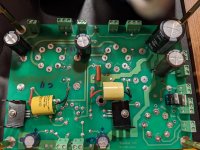
Just got the jumpers in for TR1, D3 and D4, didn't do that for some reason years ago. Had to in solder the coupling caps I installed some time ago as they were the wrong size. That was a pain!
Mounted the board in the chassis and my darn pot is in the way of the board so I'll have to move that....someone should have laid it out better...oh well wouldn't be something I worked on if there weren't a few small mistakes on the way!
Put the
Attachments

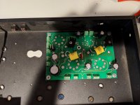
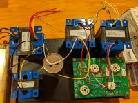
Here's a look at the inside so far, you can see I didn't plan the location of the pot very well🤷
That's unfortunate, but "stuff" happens, eh?
Progress is progress, even if there is a step backwards here and there.
Well there will be no singing today...haha, started with wiring my potentiometer, wasn't paying attention and snapped one of the legs off. I had a fake blue Alps laying around so I started to solder that one up and did the same thing. Man those things are a real pain to solder.
Well there will be no singing today...haha, started with wiring my potentiometer, wasn't paying attention and snapped one of the legs off. I had a fake blue Alps laying around so I started to solder that one up and did the same thing. Man those things are a real pain to solder.
soldering onto those tiny pins really sucks!
soldering onto those tiny pins really sucks!
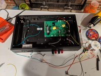
Yeah I was trying to use some Beldon sheilded wire, guage a little to thick and copper, that didn't help. Im going to temporarily wire in a 100k to test the amp.
Looks crazy but it will work for checkout
Attachments
Omitting the standby switch is a good idea. They're difficult to implement correctly to begin with, and besides there's really no good reason to use one in this amp. Just throw in a CL-140 inrush current limiter (or whatever George recommends) on the hot lead between the fuse and power transformer primary and call it good. Just keep it away from anything flammable.
Your time is much better spent working on good grounding.
Cogitech, I like the idea of the "phoolery" switch, heh, heh...
Hey Mr_Zenith,
Thanks for the idea on that. I have a combo switch/fuse IEC plug, just go ahead and place the CL90 from L/N? I have been trying to dig through some posts about this.
- Home
- More Vendors...
- Tubelab
- It's only taken 8yrs for my SSE build....