I too saw them called such when they 1st rose to prominence.
dave
and now another one, in my experience the 6H23 sounded even better, besting the 6dj8 bugle boys in our listening tests...
Thank you Tony. This means a lot coming from you
i am just a pm away....😀
I have alot of those and a dozen that have been cyroed.
dave
i liked them even out of the box from the post office..😀
More important still is understanding what causes the current distortion he's measuring.I am trying to get my head around the 2 curves. They come from the same place, the phase shift shows a reactance in the speaker, and what i think is more important is the distortion that shows up when you measure the current that is not in the volatge. It would be nice to see the residuals on those measures,
No worries. The idea that that a loudspeaker is driven by voltage source with low Z, the current into the load is merely a consequence of the voltage is a very incomplete view. I will try to explain.
Sure, if you double the voltage into a fixed load (single frequency), then the current will double. The dB-SPL output of the driver will go up by +6dB.
But the driver is responding to the doubling of the current and that is resulting in +6dB. It has to be that way, please ask any electrical engineer and it applies to all motors and a dynamic loudspeaker is a motor, a linear motor. It is just the way it is.
Two sinewaves?
No, I am not kidding, it is quite easy to show that the amplifier, when it has a low source Z, is producing two sine waves at the same time. Sounds crazy, right?
Take a look below, that is the screenshot of an oscilloscope, where it is connected up to the ONE amplifier producing TWO sinewaves in the same moment in time.
The Yellow is the voltage of the amplifier and the Red (ish) is the current of the amplifier. A voltage sine wave and a current sine wave.
Since they don't line up in time, note the current phase angle has changed by around 30 degrees, then which one of these two sine waves are we listening to? Which sine wave is getting converted to dB-SPL?
We know which one. There cannot be an argument when we know what is a fact, right?
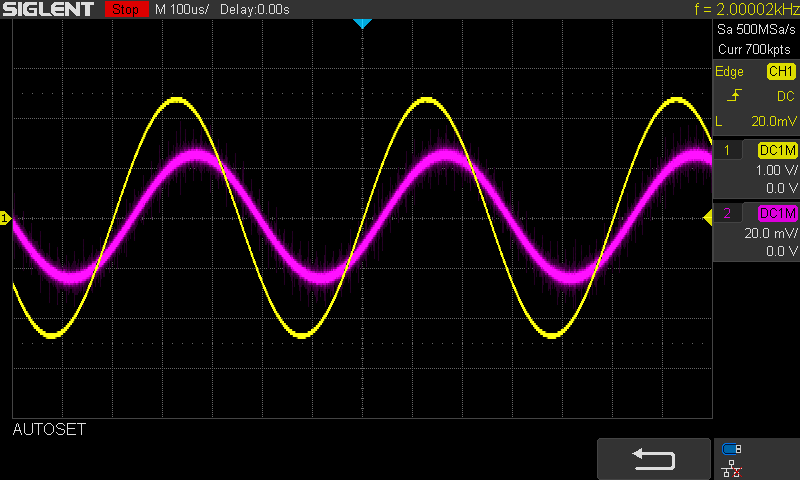
NOTE THE PHASE SHIFT.
The difference is caused by the current phase angle of the driver modifying the current.
This is not photoshopped! This is a real measurement of a Peerless HDS driver I have right here. But sinewaves are produced at the same time.
The voltage comes from the amplifier.
The current comes from the amplifier.
The amplifier is producing both sinewaves.
And at the same time.
We cannot be hearing two sinewaves, so which one?
Does the two sinewaves have the same measurable distortion?
No!
Please, you need to reinterpret your results and you might see it in a different light.
Actually, with CS the current is now being fixed, whereas under voltage drive it is not. You are now listening to the current not varying like it does under voltage drive.
Indeed your example proves what every engineer and physicist I have asked has confirmed, that the dB-SPL is proportional to the current, not the voltage. Have you heard of Michael Faraday? Current causes motion. The voltage across the terminals is incidental, the current through the voice coil is what matters.
But look again and you will see that it does indeed follow the current. The voltage is incidental. OK?
---
You mention other things, but I don't want to be seen to be hijacking the thread, not my intention.
Does tubes have a sound?
That is the topic. Maybe they do, but what if tube amplifiers sound better because they have lower distortion? But does not tubes have higher distortion? Yes, on the voltage side. But what about the current.
I believe the output transformer of a tube amplifier leads in part to a better current delivery system, and that on the current side, low distortion.
So there you are. Let me know your thoughts.
who in his right mind will claim that we can only hear one, the current sine wave and not the voltage sine wave?
please no more.....enough of this.....this is a lounge material...
Yeah but the magnetic field of the current is what moves the speakers. The voltage is needed to create current but current doesn't need to follow the voltage.the separation between voltage and currents appear only in analysis and calculations, in the real world, if we are to make something out of them, then there is real time "power"...
the power input to any speakers is what moves the cones that in turn move the air that produced the sounds that we hear....
to say current only, or voltage only is the height of folly...
Therefore if the magnetic field of the current is to act as you want it to then a current amp or a non-reactive load is required.
You can alter the power without altering the SPL, just level shift the impedance downward. As long as the current, coil turn ratio, and driver weight remain the same it won't matter.
This is why I advocate ribbon-like impedances because you can get away with amplifiers of exponentially lower heat, size, and distortion. I don't think you can decrease impedance while maintaining turn ratio and driver weight though so you'll pay with less turns and more current.
If I'm somehow wrong let me know.
It's pretty clear people aren't interested in discussing those circuits and their potential implications so I moved it over to the other thread.it would help if you explain and justify your drawings?
Last edited:
Yeah but the magnetic field of the current is what moves the speakers. The voltage is needed to create current but current doesn't need to follow the voltage.
Therefore if the magnetic field of the current is to act as you want it to then a current amp or a non-reactive load is required.
You can alter the power without altering the SPL, just level shift the impedance downward. As long as the current, coil turn ratio, and driver weight remain the same it won't matter.
This is why I advocate ribbon-like impedances because you can get away with amplifiers of exponentially lower heat, size, and distortion. I don't think you can decrease impedance while maintaining turn ratio and driver weight though.
If I'm somehow wrong let me know.
yes, and George Simon Ohm says, current = voltage/speaker impedance
so you see, there is no escaping this three elements....
but do not forget the magnetic circuit.....
.
first it is the magnetic circuit comprised of the magnet and the pole pieces and the air gaps that determine the extent of motor action, the strength of the magnets determine the flux available at the air gaps, this is what is missing in your post so i am letting you know in case you missed it....i am sure you know this already yes?
It's pretty clear people aren't interested in discussing those circuits and their potential implications so I moved it over to the other thread.
which thread was that?
first, when you post schemes, tell people what that is all about what your design goals are so people can judge what you really need...
we can then criticize your work, when someone comments on your work, that is a criticism, take is a gift not an affront...
that is how we learn...
do not fall for the trap of super triodes or beyond triodes blah blah blah...that is immaterial...
Last edited:
I can't see any non-linear distortion on the oscillogram, is this all about the phase shift?the current distortion he's measuring.
The "super triode" circuits shown by hellokitty are a particular topology where a high current device (e.g. mosfet) is used with feedback from drain to gate through the triode plate. You get the triode curves but at greatly magnified gm. It's covered extensively on the tubecad site. As opposed to the other "super tubes" discussed above which are high gm low plate resistance triodes like the 6H30p.
but the mosfets themselves have such a high gm already all by itself, Nelson Pass amps are proof...why complicate things?
oh i get it, this is diy, everything goes.... 😀
don't mind me, i was just thinking out loud....
oh i get it, this is diy, everything goes.... 😀
don't mind me, i was just thinking out loud....
Last edited:
He says he's measured distortion, probably the fuzziness in the trace. Pavel measured current distortion too in the links I showed earlierI can't see any non-linear distortion on the oscillogram, is this all about the phase shift?
Current drive of speakers and speaker distortion
"THD at amplifier output was 0.0046%, though THD distortion of speaker current was 0.111%. This is a direct influence of speaker non-linear impedance resulting in increase of current distortion. I = V/R where R is non-linear."
Last edited:
Yeah but I'm not intimately familiar with the intricacies of dynamic driver construction so I don't know the practicalities of how much flux you can get in there..i am sure you know this already yes?
This one.which thread was that?
https://www.diyaudio.com/forums/tubes-valves/348559-50w-super-triodes-stuff-3.html#post6057660
You must have missed the link
I went into more detail there.
I used an opamp for most of the loop gain instead of a mosfet.but the mosfets themselves have such a high gm already all by itself, Nelson Pass amps are proof...why complicate things?
The point of "complicating things" is the point this thread exists. It's to listen to the sound of tubes. It allows the tube to react to the load (or not) and control the output without needing to worry about driving the load current.
It's essentially a solid state amp with the transfer curves of a triode. So if a triode "sounds" like something, then it should be heard.
Last edited:
Yeah but I'm not intimately familiar with the intricacies of dynamic driver construction so I don't know the practicalities of how much flux you can get in there.
This one.
https://www.diyaudio.com/forums/tubes-valves/348559-50w-super-triodes-stuff-3.html#post6057660
You must have missed the link
I went into more detail there.
I used an opamp for most of the loop gain instead of a mosfet.
The point "complicating things" is the point this thread exists. It's to listen to the sound of tubes. It allows the tube to react to the load (or not) and control the output without needing to worry about driving the load current.
It's essentially a solid state amp with the transfer curves of a triode. So if a triode "sounds" like something, then it should be heard.
thanks will give it a look...
this board allows all ideas to flourish, just get yourself ready to get criticized, without running tantrums....you may even benefit...
many float ideas so as to get validations...be ready for a bumpy ride...
I've just made a video concerning this subject - YouTube where I compare a homebrew valve amp to a transistor amplifier, but I recorded the OP from dummy loads. The result has been mucked about digitally obviously in order to upload it Utube but there is a slight discernable difference.
Andy.
Why is Dave Brubeck's piano on the left in first part, and on the right in second part? Did you swith channels on purpose? Or by accident?
?????
The same song played throug one amp has piano on the left, played through another amp has piano on the right...you call that panning?
I call it switched channels.
The same song played throug one amp has piano on the left, played through another amp has piano on the right...you call that panning?
I call it switched channels.
Validations are my only concern. I have no use for circuits that don't perform as I wish, what a waste of time. People tend to insert their emotions and egos too much during discussion which makes it annoying though. I just want a logical discussion.thanks will give it a look...
this board allows all ideas to flourish, just get yourself ready to get criticized, without running tantrums....you may even benefit...
many float ideas so as to get validations...be ready for a bumpy ride...
As far as those tube circuits I pretty much deemed them as obsolete years ago so I don't particularly care about their validation one way or the other, I got way cooler stuff now IMO. Not that I don't want to hear thoughts and opinions because I do.
I'm only bringing them out now to gauge peoples interest since I know they are a step up from typical circuits of their kind. Maybe I can generate a little coin while giving the people what they want. Probably not but it's worth a shot.
Plus it helps the conversation of whether or not tubes have a sound.
Last edited:
- Status
- Not open for further replies.
- Home
- Amplifiers
- Tubes / Valves
- Do tubes actually sound like anything?