Bingo. That works. (I had tried all the way up to 470 with no success.)
Eliminating those caps (Miller or not) gives a huge boost to 10kHz performance....
😀

Yay
Try changing input to cascoded LSJ74 (or 2sJ74).
Use Bipolars as cascode devices.
Apply 10mA of current
Use Bipolars as cascode devices.
Apply 10mA of current
Spoke too soon. Still oscillates when I zero the offset....
🙁
Reduce open loop gain.
Or reduce open loop bandwidth. Open loop bandwidth should be greater than 20kHz, but you probably don't want more than 200kHz open loop bandwidth.
If you run output stage free of feedback then it gets a little easier making everything stable.
Or reduce both open loop gain and open loop bandwidth.
This is where the CCS or resistors that are used wiil matter, along with more or less degeneration, etc.
Maybe increase gate stoppers at input stage as well as on lateral mosfets.
Increase input stage to 10mA bias current.
Use Jfet input.
Last edited:
Damn this thing's finicky.
I lowered the resistors above the current mirror, which allowed me to lower the resistor in the middle of the second diff. No more oscillation.
Better check the 10K THD....
0.007%. 😱
I'm going to stop here for now and enjoy my success. Thanks Pico!
I lowered the resistors above the current mirror, which allowed me to lower the resistor in the middle of the second diff. No more oscillation.
Better check the 10K THD....
0.007%. 😱
I'm going to stop here for now and enjoy my success. Thanks Pico!
Itsmee,
Could you post the schematic of your amplifier if possible?
Some reading....
#13, still lots to play with, and thank you for the read.
Damn this thing's finicky.
I lowered the resistors above the current mirror, which allowed me to lower the resistor in the middle of the second diff. No more oscillation.
Better check the 10K THD....
0.007%. 😱
I'm going to stop here for now and enjoy my success. Thanks Pico!
Yeah.
It all matters.
(Note that it still has an inverted distortion/power curve. 😕)
Without seeing the curve and knowing exactly what you mean, this is to be expected with a source follower output stage with out degeneration.
If you want to change this then simply apply some resistive loading to ground at the output of the VAS, to get the distortion character you want.
You should determine by ear how much is desirable.
So much difference between R3 and R7? I don't have your K1058/J162 model, it still oscillates using Cordell models.
If you look at the above curves what can you surmise................😉
Jam
Still digesting the read
Hmm, looks like I'm stuffed, I can't remember off hand, I think Alice only makes around 30dB open loop due to the loading.
I'll add some source resistors when my replacement soldering iron arrives.
So much difference between R3 and R7? I don't have your K1058/J162 model, it still oscillates using Cordell models.
At the time I couldn't figure out any other way to get the offset near zero.
I did later on the JFET version, but I haven't gone back and update the BJT version (and I might not as the JFET version performs better anyway).
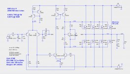
See if this one is stable for you.
Attachments
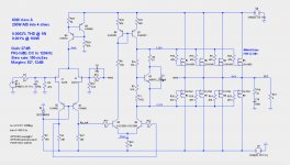
Stable, even without base resistors on 2nd diff and 33 ohm on mirror emitter resistors. I'd suggest 330 ohm gate stoppers on the jfets, cascode voltage of less than 8V to avoid high excess gate current at higher voltage and adjust R8 to ~ 5k to balance collector voltage of Q5 and Q6.
Last edited:
Hi indra1,
I've replaced R8 with a pot to adjust offset so I don't have to unbalance the first LTP resistors. I think that's the same as balancing the collector voltages of the second LTP?
I'll try out some of the other ideas.
Cheers,
Jeff.
I've replaced R8 with a pot to adjust offset so I don't have to unbalance the first LTP resistors. I think that's the same as balancing the collector voltages of the second LTP?
I'll try out some of the other ideas.
Cheers,
Jeff.
I also tried 6 output pairs for short-circuit survivability. It doesn't like driving all those gate resistors unless you slow down the front-end (I did manage to get it stable with 270ohm MOSFET gate resistors and 2K2 base resistors in the second LTP). The distortion specs obviously suffer a bit from this, as does the slew rate.
The right solution would no doubt be to add a driver stage as Jam suggested, but 3 stages is about all I can handle. 😉
Another option is to forego short-circuit survivability. It seems prone to instability anyway, so maybe we just name it BuzzBomb and say it is what it is. It'll probably sound great until it catches fire....


I have a very nice simple discrete regulator design but was kind of saving it for my own thread.
Just reading an article by Bruno Putzeys. It includes some great broad-brush-strokes on control-theory and compensation. Highlights mine.
Probably old-hat to most of you, but these tidbits will certainly help me next time I try to stabilise something like the Hitachi topology....
And finally, I leave you with this little gem (same source):
Cheers,
Jeff.
[An amplifier is made "faster"] by decreasing the compensation capacitor. Unfortunately we can't just do that. Both input and output stages are low-pass filters. Control theory tells us that the additional phase shift will cause the loop to go unstable if there's too much loop gain left, so we set loop gain to become less than 1 well below the corner frequencies of either the input or output stages.
Slew rate limiting means that an amplifier is trying to reproduce a very fast rate-of-change signal but can't. The maximum rate of change it can produce is determined by the current available to charge or discharge the compensation capacitor. This current is provided by the input stage and the maximum is the tail current Ib. When a faster rate of change is demanded, the input stage is overloaded and becomes completely unresponsive to any further change. At this point, the feedback loop stops working and is no longer able to control the amplifier.
Probably old-hat to most of you, but these tidbits will certainly help me next time I try to stabilise something like the Hitachi topology....
And finally, I leave you with this little gem (same source):
It's no proof of intelligence to open a debate pointing out the supposed "extremes" of the opinion spectrum and then taking some imagined middle ground. When person A says that 2+2=5 and person B says that 2+2=6, the most reasonable position to take is not five and a half. 2+2=5.5 can hardly be called moderate. In fact it is a very, very extreme claim.
Cheers,
Jeff.
- Home
- Amplifiers
- Pass Labs
- JamJar: an HPA-1-inspired power amp