Nisbeth, if you decide to create (lay out) a new improved printed circuit board for the ACP+, including those two trimmer potentiometers you mentioned, please permit me to offer a couple of suggestions for additional modifications that you might want to think about incorporating:
- Include a PCB footprint for an optional power on-off switch. People who don't want it can of course solder in a jumper wire.
- Include a PCB footprint for a 3.5mm TRS jack, for people who want to plug in headphones or earbuds that don't have a 1/4" plug. Do it in whatever way is easiest for you; if it means the 3.5mm jack is unswitched, no big deal.
- Include a couple of relays, one per channel, that implement switchable gain. And of course a footprint for the switch that activates/deactivates the relays. Good choices for gain might be +7dB (low gain setting), +17dB (high gain setting). But since you're the one designing the board, you get to make the final decisions about gain numbers.
Wouldn't it make sense to make this adjustable (trimpot)? The same would apply to R4 to make the CCS-current adjustable (as some people discussed a few pages back?
Not generally. Being cap coupled, you don't really need to trim it unless
it's seriously out of spec. The amplifier is very tolerant of variations,
intentionally so.
I like big caps, and I cannot lie.
Thanks for the help, PRR!
I got to that end of the pig already: Output cap is now a 3900uF Panasonic FC. Nelson Pass is my unrivaled transistor guru, but I also know him as a multilevel entertainer and provocateur, so when he leaves empty space within the silk screening, I know he's looking for a reaction.
Sure, film caps can be pricey, but I'd been dying to try these unpretentious ones for $3, so in they went: 3uF Vishay 1848 MKP from Mouser, my favorite boutique. Pearls before swine? It's never sounded better, and the smoke is still kept safely inside.
Now, did someone mention more gain? I could use a couple of dB...
I bet there was also a bleed resistor draining the Big Film Cap. So yeah- the guts of ACP are supposed to bias-hald-way up the supply voltage, you slammed it to the floor (zero V), it can't be happy. You NEED a C1.
> What is the smallest input cap
The stock input R is 75k. Reactance chart tells us that a 0.1uFd against 75k is 22Hz, which is rather high for "high"-fidelity (-1dB @ 44Hz, so shaves deep bass). That's not considering the value of the BFC in the CD box, or all the bass-cuts from the studio microphone to the ACP.
1uFd would be 2.2Hz, little effect on music, but is a pretty big film cap for me. (Some folks don't mind the size and expense.)
A half-mike might be a happy compromise.
The cap has sure bias, so an electro works fine, and 1uFd is very cheap in electrolytic, but electros distort near cut-off.
What works WELL for many designers is to pick the electro about 100X bigger than needed for bass response. This ensures the AC/Audio voltage across the cap is super-small, so nothing to distort. All your (older) music came through hundreds of very large electros. If we assume recordings don't have much under 50Hz (few do) and 0.1uFd is just OK, then 10uFd (100X bigger) should be "inaudible". (Yes, I know: you saw it, you will still hear it.)
I think Mr Pass knows a LOT about musical sound. Not only for his $13,000 products, but also what works above its price-point.
There is a different HACK. Modify the known-good circuit. Your own risk.
The JFET can bias with a large resistor. Using 1Meg a 0.01uFd cap is almost good enough.
Lift the Gate leg of Q1 and bend it up. Lift the "-" leg of C1, turn and bend it up. Get a 1Meg resistor and some small wire. Re-rig it as shown, air-wired. New cap "C13", look in your 0.1u box; if you have a 0.05u or 0.27u which looks sweet, use what you like.
However ALL the sound to the headphones has to go through C3. And the flaws in any headphone overwhelm the flaws of even an electrolytic cap. We may be lipsticking the wrong end of the pig.
Thanks for the help, PRR!
I got to that end of the pig already: Output cap is now a 3900uF Panasonic FC. Nelson Pass is my unrivaled transistor guru, but I also know him as a multilevel entertainer and provocateur, so when he leaves empty space within the silk screening, I know he's looking for a reaction.
Sure, film caps can be pricey, but I'd been dying to try these unpretentious ones for $3, so in they went: 3uF Vishay 1848 MKP from Mouser, my favorite boutique. Pearls before swine? It's never sounded better, and the smoke is still kept safely inside.
Now, did someone mention more gain? I could use a couple of dB...
Attachments
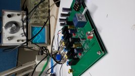
Here is my finished ACP+. I had assembled the board at BAF2019. Thanks go to Nelson and everyone involved who contributed time and parts to make this a success.
Originally I was going to sandwich the board with plexiglas, but I decided in the end to go super budget and used what I had on hand, which was half inch plywood. I did purchase some M4 standoffs and screws, and a 2.1mm DC pcb power jack and plug to finish it off. I have also purchased an inline power switch that has male and female 2.1mm plugs that will insert into the DC power line.
I just purhased a pair of AKG K240 Studio headphones to go with the ACP+. It was only $70 CAN (available in the USA for $44 USD), so it is not the best headphones available, but I have high hopes for it.
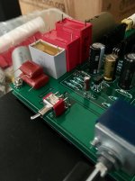
Now these headphones are 55 ohm and the ACP+ is optimized for 32 ohm. I decided to modify the ACP+ so that it sees 32 ohm with the headphones in the circuit. I inserted 82 ohm resistors between signal out and Ground, and also replaced the 32 ohm resistors at the switched preamp outs to Ground (R16 and R17) with 56 ohm resistors. The net result is in preamp mode, the 82R and 56R are in parallel, giving 33R. With the headphones plugged in, the 56R is switched out, the 82R is paralleled with the headphone's 55R, giving 33R.
One other thing I did was I paralleled the 10uF input capacitors with 35 cent Wima MKS 1uF film capacitors. They were in my spare parts box so I threw them in.
After burning in the AKG phones with the ACP+ and FM tuner for about 80 hours, I started to listen to them at 11 o'clock last night. Fed by a TDA1541A NOS dac, I enjoyed the sound of this combination so much that I did not stop until 1:30am. The AKGs lacked extreme low bass, but overall I was very happy with the sound. I don't have any other headphones/amp to compare with, but good sound is good sound.
Today I am listening to the ACP+ as a preamp in my system and again, the sound is very good. I'm not missing my Luminaria preamp (but it will go back in).🙂


Originally I was going to sandwich the board with plexiglas, but I decided in the end to go super budget and used what I had on hand, which was half inch plywood. I did purchase some M4 standoffs and screws, and a 2.1mm DC pcb power jack and plug to finish it off. I have also purchased an inline power switch that has male and female 2.1mm plugs that will insert into the DC power line.
I just purhased a pair of AKG K240 Studio headphones to go with the ACP+. It was only $70 CAN (available in the USA for $44 USD), so it is not the best headphones available, but I have high hopes for it.
Now these headphones are 55 ohm and the ACP+ is optimized for 32 ohm. I decided to modify the ACP+ so that it sees 32 ohm with the headphones in the circuit. I inserted 82 ohm resistors between signal out and Ground, and also replaced the 32 ohm resistors at the switched preamp outs to Ground (R16 and R17) with 56 ohm resistors. The net result is in preamp mode, the 82R and 56R are in parallel, giving 33R. With the headphones plugged in, the 56R is switched out, the 82R is paralleled with the headphone's 55R, giving 33R.
One other thing I did was I paralleled the 10uF input capacitors with 35 cent Wima MKS 1uF film capacitors. They were in my spare parts box so I threw them in.
After burning in the AKG phones with the ACP+ and FM tuner for about 80 hours, I started to listen to them at 11 o'clock last night. Fed by a TDA1541A NOS dac, I enjoyed the sound of this combination so much that I did not stop until 1:30am. The AKGs lacked extreme low bass, but overall I was very happy with the sound. I don't have any other headphones/amp to compare with, but good sound is good sound.
Today I am listening to the ACP+ as a preamp in my system and again, the sound is very good. I'm not missing my Luminaria preamp (but it will go back in).🙂
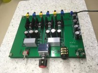
I decided on this simple case because firstly, it is simple, but mainly because it allowed me to make use of the pcb mounted jacks, switch, and pot without having to carefully align holes to a case front and back, or needing to provide additional switch and jacks on an enclosed case.
However, the idea is not original. Most notably, the late Don Garber (Fi Audio) cased his tube preamps and SET amplifiers in similar fashion, except he used aluminum plate.
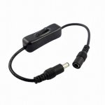
As mentioned previously, I am also adding an external inline switch so I can turn the ACP+ on and off without unplugging the power. It plugs into the 2.1mm power plug and jack that I installed.
However, the idea is not original. Most notably, the late Don Garber (Fi Audio) cased his tube preamps and SET amplifiers in similar fashion, except he used aluminum plate.
As mentioned previously, I am also adding an external inline switch so I can turn the ACP+ on and off without unplugging the power. It plugs into the 2.1mm power plug and jack that I installed.
Attachments
Nice job on the case! Looks like we're on the same track! I like how you can still see the writing on the groundplane board. I'm thinking of flipping mine upside-down, so indicator light and headphone jack are to the left of the knob. But you could orient yours either way!


- Home
- Amplifiers
- Pass Labs
- Amp Camp Pre+Headphone Amp - ACP+