Hello
I have a wonderful full functioning TA-N88B and I would like to address problem areas and make it safe to use daily.
Here is some info on vintageknob that I would like follow
I am looking for help with capacitor selection. For the bigger ones, which are
2200uf 200v and 5600uf 100v I have found some Nichicon which I think will work, but I would have to jump the 5600uf up to 6800uf. Would that be a mistake or not advised?
LNT2D222MSE Nichicon | Mouser
LNT2A682MSE Nichicon | Mouser
I am looking for any input on which caps to use for he lower voltage/value caps
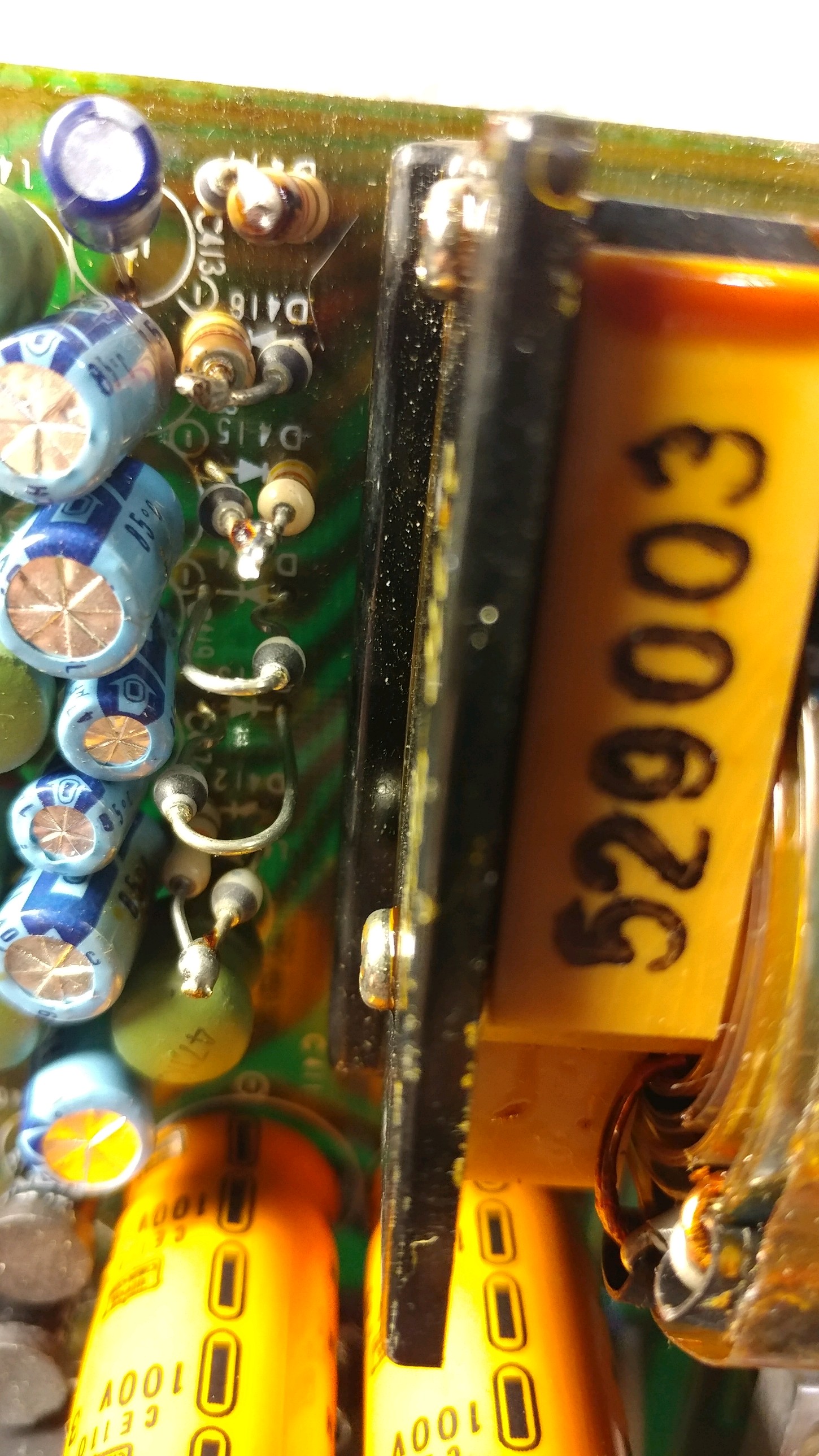
Now for the part where he mentions changing the rectifier diodes. I have pics of whats in there now and it looks like maybe some work has been done to this amp already. Any information or direction on this area would be great
Thanks for any help or insight. I really want to do it right and keep this things playing for a long time to come.
I have a wonderful full functioning TA-N88B and I would like to address problem areas and make it safe to use daily.
Here is some info on vintageknob that I would like follow
As far as true weak points in an N88, that would be the power supply capacitors, in particular the main filter cap, which is mounted on the housing, and said housing also doubles as a heatsink - this shortens the life of the cap to "only" some 10 years or so. Ditto low voltage filtercaps on the output of the PLPS.
These should be replaced with low ESR caps, and the rectifier diodes replaced with 100V Schottky types (these were not available when the N88 was made), with a small series resistor (0.5-1 ohm or so).
The original circuit has standard diodes, and due to surge currents, these tend to heat up the electrolytics, which then subsequently fail. The biggest problem here is the failure of one of the bias supplies, which invariably kills the VFETs.
I don't think it would be the load, even at the highest power, unless very inductive or capacitive, that kills an N88, but rather the failure of said electrolytics
I am looking for help with capacitor selection. For the bigger ones, which are
2200uf 200v and 5600uf 100v I have found some Nichicon which I think will work, but I would have to jump the 5600uf up to 6800uf. Would that be a mistake or not advised?
LNT2D222MSE Nichicon | Mouser
LNT2A682MSE Nichicon | Mouser
I am looking for any input on which caps to use for he lower voltage/value caps
Now for the part where he mentions changing the rectifier diodes. I have pics of whats in there now and it looks like maybe some work has been done to this amp already. Any information or direction on this area would be great
An externally hosted image should be here but it was not working when we last tested it.
An externally hosted image should be here but it was not working when we last tested it.
Thanks for any help or insight. I really want to do it right and keep this things playing for a long time to come.
Attachments
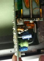

Any idea why the electrolytics are on such long leads ?
If the amp is subject to any vibration they will eventually fracture.
If the amp is subject to any vibration they will eventually fracture.
Note that this is a class D amplifier (yes, 1970's!) and those elcaps are in the SMPS. So make sure you select caps that are rated for high frequency switching applications.
Note that most of the failures of this amp are from the SMPS, and that almost no repair sevice wants to touch them!
So you either should be very careful and/or expert, or leave them as they are. Replacing those caps does nothing for sopund quality but carries a real risk that something goes wrong.
If your hobby is 'capacitor rolling' there are other amps that are much more forgiving.
Jan
Note that this is a class D amplifier (yes, 1970's!) and those elcaps are in the SMPS. So make sure you select caps that are rated for high frequency switching applications.
Note that most of the failures of this amp are from the SMPS, and that almost no repair sevice wants to touch them!
So you either should be very careful and/or expert, or leave them as they are. Replacing those caps does nothing for sopund quality but carries a real risk that something goes wrong.
If your hobby is 'capacitor rolling' there are other amps that are much more forgiving.
Jan
No not into capacitor rolling, Im into making this rare amp safe to use daily without constantly fearing Im gonna loose a vfet. This is a working example and I just wanna keep it that way. The capacitors seem to be the main culprit of failure. I can see some have been changed and Im gonna change them all. Sony even put out a service bulletin changing the value of one capacitor to reduce frequent failure. I am here for advice on getting the right caps in the right spot, can someone help me with that?
Any idea why the electrolytics are on such long leads ?
If the amp is subject to any vibration they will eventually fracture.
Not sure but I will make them shorter when I replace. I dont think they are all that long on the whole amp. I was trying to show those diodes and the warped board. I was wondering if those diodes and resistors like that are original or if they had been changed to what the gentleman on the vintageknob recommended.
Thanks for the replies really like soaking this info up
Hey ebk231,
I lived with that amp [back in the day] it is / was something very special. The (most capable) service tech at our store, was eventually stumped by the amp, at a point unable to fix it... If I recall correctly. the store demo model developed power supply issues. We were all bummed, to see it shelved... never to play again.
I have used many of the Nichicon LNT caps, they are remarkable, smooth and dynamic... bypassed with a (Wima) film cap. I like their high temp rating, use them as a long life component, a customer can bake their amp in use and not aged the cap so readily....
I applaud you, the comment about, 'making the amps safe for daily use'. Very wise to be preemptive in your long range plans... I would do the same.
GOOD LUCK MAN! That amp deserves the attention and TLC...
No not into capacitor rolling, Im into making this rare amp safe to use daily without constantly fearing Im gonna loose a vfet. This is a working example and I just wanna keep it that way. The capacitors seem to be the main culprit of failure. I can see some have been changed and Im gonna change them all. Sony even put out a service bulletin changing the value of one capacitor to reduce frequent failure. I am here for advice on getting the right caps in the right spot, can someone help me with that?
Hey ebk231,
I lived with that amp [back in the day] it is / was something very special. The (most capable) service tech at our store, was eventually stumped by the amp, at a point unable to fix it... If I recall correctly. the store demo model developed power supply issues. We were all bummed, to see it shelved... never to play again.
I have used many of the Nichicon LNT caps, they are remarkable, smooth and dynamic... bypassed with a (Wima) film cap. I like their high temp rating, use them as a long life component, a customer can bake their amp in use and not aged the cap so readily....
I applaud you, the comment about, 'making the amps safe for daily use'. Very wise to be preemptive in your long range plans... I would do the same.
GOOD LUCK MAN! That amp deserves the attention and TLC...
Hi Doc
Thanks for the encouraging words, it is appreciated. Im glad to hear your fond memories of this amp. I listened to it for just a short period and knew I wanted to make it safe to use. Beyond its known legendary status this particular amp came from a Sony collector who passed recently. I got to know him over the last few years and Im really happy to have it.
I understand why people dont want novices to ruin special gear. I also understand that this needs to be done, and a lot of folks cant justify the cost of having a specialist do this. Im about finished with the work and Im glad I did it, about half the caps were in the 25%-35% range, 5 or so where 35%+, and the rest being 10%-25% . Tested on my fluke 115.
I was not able to run the LNT caps because of size. I really liked them for the looks and screw terminals to keep it very original looking.
For the large 2200uf 200v cap I got this one from Kemet. Seems to be a great a cap and fits like original, but no screw terminals.
ALT22A222DF200 KEMET | Mouser

For the large 5600uf I went with Cornell Dubilier and Im still waiting on these
383LX562M100A062 Cornell Dubilier Electronics (CDE) | Capacitors | DigiKey
For the rest I used Nichicon KA in the amp section and Nichicon PJ in the power supplies. I also tried to up the voltage rating a step or two where I could


I also did a couple things from the service bulletins
Change R321 originally a 10k down to a 8.2k this is suppose to help with shut off noise
Change C154 & C104 originally 220uf 6.3 to 100uf 10v Bulletin states that this should eliminate having to do frequent changes.
I hope this info helps someone in the future and welcome more input.
I have the same model that I purchased new in the early 80's. Very much the same condition as yours and I have been searching for suitable replacement caps for several years. I wanted to ask how you came to select the ones you mention in your posts and if you got them installed how are they performing?
I have the same model that I purchased new in the early 80's. Very much the same condition as yours and I have been searching for suitable replacement caps for several years. I wanted to ask how you came to select the ones you mention in your posts and if you got them installed how are they performing?
Hello
I researched for quite a long time myself. I chose the caps I did mostly because they were all I could find that would fit, at least for the large ones. They were also the highest quality I could find for a reasonable price. As far as choosing Nichicons my research shows that the PJ series seem to be good for fast switching power supplies. The KA & KT seem to be good for signal path.
I had the amp up and running and one channel was a was a little low in volume. When I was doing some checking I arced the probe and took out a couple of the v fets
 I am now on the hunt for some replacements and hope maybe someone here can help.
Here is a link to a Japanese blog that I found to be really helpful.
[ TA-N88 パワーアンプ レストア ] | やっぱ物欲には勝てません-完全解脱はいつの日か? - 楽天ブログ
With the info I gained by reading that and a lot of trial and error I know when I get the vfets I will get it right. I learned a lot taking on the project and I made a costly error, but I will get this amp back to like someday.
Not to be so helpfull, but I've removed the vintage SMPS from my TA-N86 (the 'lighter' member of this esprit family) altogether. It proved to be unreliable and noisy.
Replaced with 4 12V/60W transformers (serial/parallel switched for B/A operation), greatz-bridge and cap-pack. Flawless.
Replaced with 4 12V/60W transformers (serial/parallel switched for B/A operation), greatz-bridge and cap-pack. Flawless.
Not to be so helpfull, but I've removed the vintage SMPS from my TA-N86 (the 'lighter' member of this esprit family) altogether. It proved to be unreliable and noisy.
Replaced with 4 12V/60W transformers (serial/parallel switched for B/A operation), greatz-bridge and cap-pack. Flawless.
Got any v-fets? 😀
Got any v-fets? 😀
If I had them, I would sell them.
Though the TA-N86 is equipped with BJT's, no Vfets.
Curious to realize that Vfets, by nature gifted with output characteristics alike triode tubes, in this specific design were unly used to switch the power rails quickly to the output, where mosfets would do the same more efficient.
Seems Sony missed the point of it completely, in my humble view.
I'd rather use my own compound substitutes made of commen parts, but in overall I don't like the TA-N88 design and switching topology.
I have seen some N88s that have been switched to mosfets but without any info on how it was done. Designing something like that is way out of my league. Would you be willing to help make a compound substitute?
Would you be willing to help make a compound substitute?
Ohww... now that's a hard blow on the head.
Considerations...
in short: never no
I'm fully aware there're three solutions to get this done, other then in tube dimensions, symmetrical in semisilicon, thus p-channel semitubes also.
One is used daily unaware, second is used proper in other config as cascode, but ideal acting as Vfet or tubetriode on demand and full no frequency depending config consisting of fet-bjt or bjt-bjt (even fet-fet) and plus max 3 resistors compound is my discovery not suitable for hobby or industry. By moral reasons only. It's so...
sorry, full short here
Hello
I researched for quite a long time myself. I chose the caps I did mostly because they were all I could find that would fit, at least for the large ones. They were also the highest quality I could find for a reasonable price. As far as choosing Nichicons my research shows that the PJ series seem to be good for fast switching power supplies. The KA & KT seem to be good for signal path.
I had the amp up and running and one channel was a was a little low in volume. When I was doing some checking I arced the probe and took out a couple of the v fets
Here is a link to a Japanese blog that I found to be really helpful.
[ TA-N88 パワーアンプ レストア ] | やっぱ物欲には勝てません-完全解脱はいつの日か? - 楽天ブログ
With the info I gained by reading that and a lot of trial and error I know when I get the vfets I will get it right. I learned a lot taking on the project and I made a costly error, but I will get this amp back to like someday.
Oh wow. I am so sorry to hear that about the v-fets. Back when I first started looking into restoring my unit it was possible to find them on Ebay. They were rare but there wasn't a lot of interest in them outside of those looking to repair the Sony units.
After Nelson Pass designed his SIT amp and released the information for the diy project utilizing the same v-fet pair as the TA-N88 they quickly disappeared. There was talk of new ones being manufactured but apparently hasn't happened.
There is a good overview on The Vintage Knob site discussing the TA-N88's theory of operation with some proposed changes to improve the original design. Replacing the v-fets with mosfets is mentioned but little detail is given by the author.
I wish I knew something more helpful. If I come across anything I will post back and let you know. Thank you for your time in answering my question and I sincerely hope you have good luck in finding the parts to repair your amp!
Thank you, I really appreciate it. I will get it someday Im stubborn like that, plus I love this old Sony gear.
Im surprised nobody is trying to make modern substitutes. I would think someone could make some money with the prices they are commanding.
I hope my mishap does not discourage you. Wish I knew what I do now when I started working on this amp. My advice to anyone who wants to work on one of these would be to take out the driver boards and the vfets. Then change out the parts you wish to replace. I found the diodes in the power supply to be troublesome and I would check every part on the driver board. Then go through all the adjustments needed for replacing the vfets this is outlined in the service manual and a bit more detail from the Japanese blog that I linked.
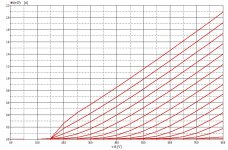
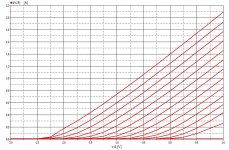
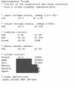
Screenshots from historic simulations of a solopolarity bjt-bjt configuration, but adaptable to Vfet with fet-bjt compounds to suit J28/K82 specs.
Just plain screenshots with some obvious valuables grayed out. (sic)
It can be done. Priceless.
Oh, thanks to Trond Ytterdal for generously providing me that perfect Aimspice package!
Just plain screenshots with some obvious valuables grayed out. (sic)
It can be done. Priceless.
Oh, thanks to Trond Ytterdal for generously providing me that perfect Aimspice package!
Attachments
Last edited:
If I had them, I would sell them.
Though the TA-N86 is equipped with BJT's, no Vfets.
Curious to realize that Vfets, by nature gifted with output characteristics alike triode tubes, in this specific design were unly used to switch the power rails quickly to the output, where mosfets would do the same more efficient.
Seems Sony missed the point of it completely, in my humble view.
I'd rather use my own compound substitutes made of commen parts, but in overall I don't like the TA-N88 design and switching topology.
Well, you should look at it historically. VFETs were developed before MOSFETs and even today getting MOSFETs with such a low input capacitance (which is also fairly linear) is pretty much impossible.
There are things not generally known about VFETs (SITs).
1) This is still the fastest switching semiconductor built in silicon. While the triode characteristic is not ideal for switching on one hand, it is on another - the switching is 'soft' with smooth changes in impedance which reduces the need to use various RC(D) snubbers. This is particularly important in class D operation where the balance between dead time and cross-conduction is extremely important.
2) VFETs are thermally stable. The low Gm variety Sony made is virtually tempco 0 even with great variations in current. Far lower than MOSFETs and untouchable by any BJT. This is again important in a class D output stage as it can be 'statically' adjusted for best transition vs crossconduction and does not require anything to track this with temperature.
3) While Rdson is failry large with Vgs=0, there is also a positive gate and gate current region of operation where Rdson falls precipitously - often to 1/10th of the Vgs=0 figures. That is not completely up to par with modern MOSFETs but FAR better than then current MOSFETs, which could rarely go below Rrdon ~ 1 ohm. 2SK82/2SJ28 will go down to 0.2 ohms or less even for a few mA of gate current. And that with about 200pF Cgs, which does increase for lower Vgs (just like for MOSFETs) but to about 500pF at most, that's a factor of 2-3 lower than even modern MOSFETs for similar voltages and currents. The N88 gate driver circuit makes use of this.
4.) Note that VFETs were originally developed for switching purposes, which is also why Nelson Pass could get the recipe for some derived from what was originally a semiconductor for a military application. Usually this is a switch for radar pulse generation - the shorter the pulse, the less the 'blind' area is around a radar as it cannot simultaneously transmit and receive a pulse - the radar is 'blind' for any distance closer than the length of the transmitted pulse, which translates to a certain distance through the time it takes for the pulse to propagate through space.
All of that contributes to a VERY fast output stage. Even with the relatively simple BJT driver, the N88 manages to do 80-100ns transition times from one to the other power supply (a 160V slew - translates to 1.6kV/us).
Rebuiklding the N88 with MOSFET outputs is a HUGE mod.
It requires a completely different driver circuit which also needs to be shfted in voltage from 'above' the main power rails to 'below' since the MOSFETs are engancement mode, and VFETs are depletion mode. This requires rebuilding the power supply including the main power transformer (which is a ferrite cored switching one).
Secondly, the gate drive to the MOSFETs needs to be minimized in amplitude to insure the required switching characteristics but at the same time not go into the gate capacitance modes where the stored charge increases drastically.
And then, the required gate drive current is much higher. The fact that the N88 works with a 500kHz carrier (this is about 2x higher than regular class D amps with discrete outputs) does not help.
Finally, the N and P MOSFETs should be chosen VERY carefully, for minimum stored charge and more importantly and extremely difficult, about the same charge for the N and P part.
What you run into in this case is the utter disappearance of P-channel switching MOSFETs, because N channel ones are faster (can't avoid physics) and thus got much more attention to make them better. Meanwhile VFETs have some different constraints in this regard and Sony went a long way to make them surprisingly complementary.
What this boils down to is that if you want to do a MOSFET conversion, you will likely need to use lateral MOSFETs, which will saddle you with yet another problem - while the case outline is the same (TO3), the pinout is not the same - laterals gave source on the case, VFETs (like MOSFETs) have drain on the case. Another possibility (but with worse constraints on the driver) would be to get old style IRFP9240 and IRFP340 (yes, the N-ch should be for a higher breakdown voltage as this balances out electrical complementarity in other regards).
Last edited:
Regarding parts:
6800uF instead of the original 5600 will work just fine.
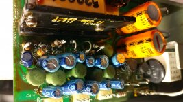
The SMPS has local capacitors, note largr yellow/orange ones, these are the first filters right after the main supply rail rectifiers. There are several that will fit, though you might have some trouble sourcing 100V parts, Panasonic, Kemet, Elna, Nichicon all have low ESR SMPS caps.
Note the light blue caps, these are for the various extra supplies inlcluding bias supplies (there is a IIRC 50V and -1.5V power supply per each main rail, to higher voltage is to switch off the VFET and the lower one is to switch it fully on). If the low 1.5V supply fails the amp will not be very efficient as it will not be able to fully switch on the VFET but it will not fail (it will trip the temperature trip and will heat up a lot). If the 50V extra rails fail, the VFETs can't turn off on that side and may eventually fail (although the overcurrent circuit switches off the main supply), They can't also turn off completely if the caps have lost capacitance which means there will always be cross-conduction and the amp will again heat up and trip the temperature protection - it's output stage operates in deep class C (as far as conduction goes) and as these fail, it will slip into class B and even AB.
Note that on your amp the light blue caps are still original so these MUST be changed. They can also be bypassed (on the bottom of the PCB) with small value quality chip ceramics. The diodes have series resistors which should be replaced by the same values except he diode would ideally be replaced with a Schottky part. Also, solder the resistors so that they are as far as they can be from the electrolytics.
The 220uF 6.V cap is a tantalum cap in the feedback loop if I remember correctly. Today we have also good enough bipolar caps and solid electrolyte caps that can be used as replacements, the important parameter is leakage current. The cap MUST be replaced if the power stage fails as it will get damaged by a too high voltage across it.
Also, make sure to check the various relays in the amp, here are separate relays that switch off the output and the power as a form of protection.
6800uF instead of the original 5600 will work just fine.
The SMPS has local capacitors, note largr yellow/orange ones, these are the first filters right after the main supply rail rectifiers. There are several that will fit, though you might have some trouble sourcing 100V parts, Panasonic, Kemet, Elna, Nichicon all have low ESR SMPS caps.
Note the light blue caps, these are for the various extra supplies inlcluding bias supplies (there is a IIRC 50V and -1.5V power supply per each main rail, to higher voltage is to switch off the VFET and the lower one is to switch it fully on). If the low 1.5V supply fails the amp will not be very efficient as it will not be able to fully switch on the VFET but it will not fail (it will trip the temperature trip and will heat up a lot). If the 50V extra rails fail, the VFETs can't turn off on that side and may eventually fail (although the overcurrent circuit switches off the main supply), They can't also turn off completely if the caps have lost capacitance which means there will always be cross-conduction and the amp will again heat up and trip the temperature protection - it's output stage operates in deep class C (as far as conduction goes) and as these fail, it will slip into class B and even AB.
Note that on your amp the light blue caps are still original so these MUST be changed. They can also be bypassed (on the bottom of the PCB) with small value quality chip ceramics. The diodes have series resistors which should be replaced by the same values except he diode would ideally be replaced with a Schottky part. Also, solder the resistors so that they are as far as they can be from the electrolytics.
The 220uF 6.V cap is a tantalum cap in the feedback loop if I remember correctly. Today we have also good enough bipolar caps and solid electrolyte caps that can be used as replacements, the important parameter is leakage current. The cap MUST be replaced if the power stage fails as it will get damaged by a too high voltage across it.
Also, make sure to check the various relays in the amp, here are separate relays that switch off the output and the power as a form of protection.
- Status
- Not open for further replies.
- Home
- Amplifiers
- Solid State
- Sony TA-N88B recap and parts selection advice