Having a brain fart this morning.
Will the following schematic work or will there be some kind of short?
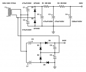
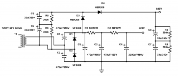
Background: I use a 120V coil to get 320VDC B+ for an amp. I need 560V for a driver stage, and I'm trying to get the voltage without adding another supply.
Cheers.
Koda
Will the following schematic work or will there be some kind of short?
Background: I use a 120V coil to get 320VDC B+ for an amp. I need 560V for a driver stage, and I'm trying to get the voltage without adding another supply.
Cheers.
Koda
Attachments
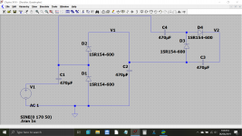
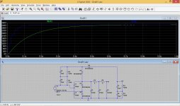
It is possible to graft a low-current, half-wave doubler to a so-called full-wave doubler to get a low-current quadrupler together with a relatively high current doubler:
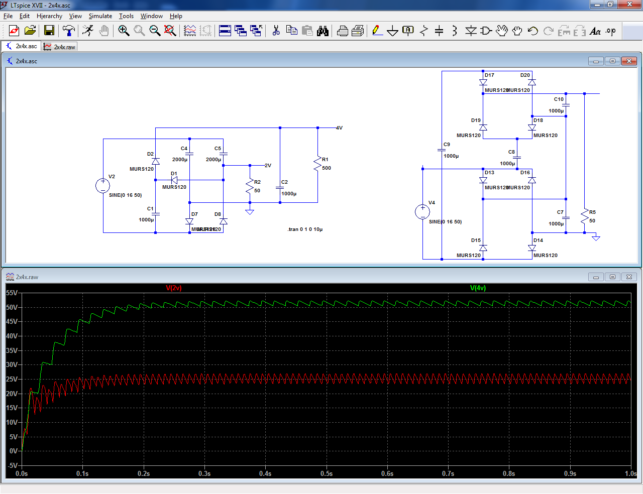
Note that the so-called "full-wave doubler" is a misnomer: it looks like the real thing because the ripple is at 2*Fin, but the individual capacitors have their charge replenished only once per cycle.
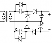
As an example, I have included a true full-wave doubler on the right: it requires 8 diodes, and to my best knowledge, it is not possible to reduce that number, which makes it highly unattractive.
Note that the so-called "full-wave doubler" is a misnomer: it looks like the real thing because the ripple is at 2*Fin, but the individual capacitors have their charge replenished only once per cycle.
As an example, I have included a true full-wave doubler on the right: it requires 8 diodes, and to my best knowledge, it is not possible to reduce that number, which makes it highly unattractive.
Attachments
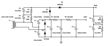
Note that you might want to include an antiparallel diode with C1 like Mona/Ketje did, to protect it against possible startup inversions, but many designs dispense with it, and it also depends on the value of C1 relative to other caps in the circuit.
Tube TV supplies of the sixties/early seventies never used one: at most, the only concession was to make C1 bipolar (silicon rectifiers were expensive back then)
Tube TV supplies of the sixties/early seventies never used one: at most, the only concession was to make C1 bipolar (silicon rectifiers were expensive back then)
")
Tiny error around C9? Polarity is backwards?
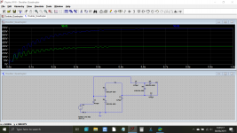
The load for the quad is 20mA. It will be LCRC filtered to output 550V or so.
It is indeed 3300uF. This amp idles at 480mA... Peaks 1.5A. It also allows such small and less wasteful resistors and still makes a good filter.
The load for the quad is 20mA. It will be LCRC filtered to output 550V or so.
It is indeed 3300uF. This amp idles at 480mA... Peaks 1.5A. It also allows such small and less wasteful resistors and still makes a good filter.
Last edited:
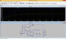
Here is the .asc file if you or anyone else wants a play. I'll look in later but I think you should try it with added load corresponding to the currents you will draw. The cap peak currents will be high... you need really good caps for this and also you might find a little added resistance to the caps would cut down the peak currents dramatically and increase the cap life significantly.
Attachments
- Status
- This old topic is closed. If you want to reopen this topic, contact a moderator using the "Report Post" button.
- Home
- Amplifiers
- Power Supplies
- Voltage doubler/quadrupler